Unmanned aerial vehicle undercarriage and anti-falling energy storage method

A technology for landing gear and drones, applied in the field of drones, can solve the problems of weak battery power, heavy take-off weight, and fast descent speed, and achieve the effects of reducing instantaneous power, good buffering effect, and reducing power consumption

Pending Publication Date: 2022-04-01
重庆交通大学绿色航空技术研究院
View PDF0 Cites 0 Cited by
  • Summary
  • Abstract
  • Description
  • Claims
  • Application Information

AI Technical Summary

Problems solved by technology

The landing gear of domestic vertical take-off and landing drones mostly uses skid-type landing gear with two poles on both sides or four pillars as the landing gear. These common structures can basically meet the take-off and landing performance requirements of small vertical take-off and landing drones, but there is a single structure , poor cushioning performance, poor stability, and can not protect the UAV in special circumstances during landing; compound wing vertical take-off and landing UAVs have a large take-off weight, and have high requirements for the load-carrying of the landing gear and the stability of the aircraft during landing. Wing vertical take-off and landing drones only rely on four rotors to complete the landing when they land vertically, and there is a high possibility of abnormal landing during the landing phase. For example, the uneven power of the four rotors causes the drone to tilt; Due to the weakening of the battery power, the power system cannot reach the set pulling force, resulting in too fast descent. Ordinary landing gear will cause the UAV to receive excessive impact force, resulting in damage to the fuselage or damage to the precision instruments in the cabin due to huge impact force.
[0003] The landing gear of drones on the market has a single function, which cannot protect the drone against special circumstances during landing, nor can it store the energy during the descent to reduce the energy consumption of the drone
Traditional skid landing gear can absorb limited energy only by its own deformation

Method used


Image

  • Unmanned aerial vehicle undercarriage and anti-falling energy storage method
  • Unmanned aerial vehicle undercarriage and anti-falling energy storage method
  • Unmanned aerial vehicle undercarriage and anti-falling energy storage method

Examples


Embodiment 1

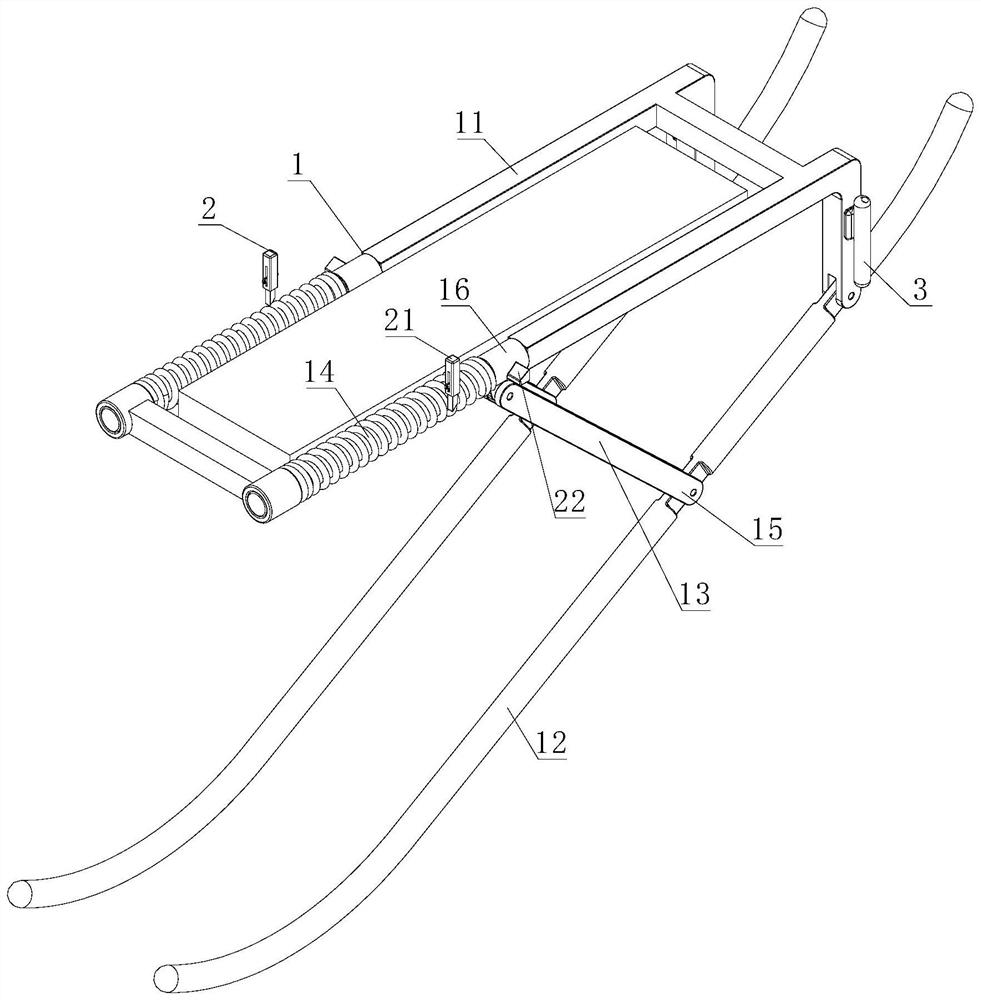
[0030] like Figure 1-3 As shown, a kind of unmanned aerial vehicle landing gear, comprises landing gear body 1, and described landing gear body 1 is folded / compressed rear shock absorption, and described landing gear body 1 is provided with energy storage device, and described landing gear body 1 is folded After being compressed, the energy storage device is charged, and the energy storage device is used to provide power when the landing gear body 1 is deployed. It can be understood that during the folding / compression process of the landing gear body 1, the energy storage device can be charged through its mechanical movement, so as to ensure that the stored energy can be used when the UAV takes off. power, so as to achieve the purpose of reducing energy consumption.

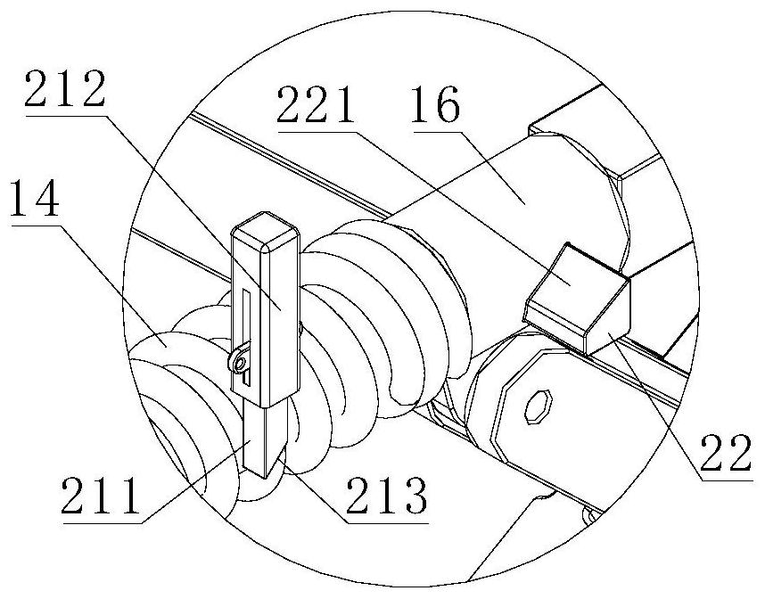
[0031]The landing gear body 1 includes a connecting frame 11 and a contact frame 12. One end of the connecting frame 11 and the contact frame 12 is hinged, and the fixed end 15 of the sliding rod 13 is hinged o...

Embodiment 2

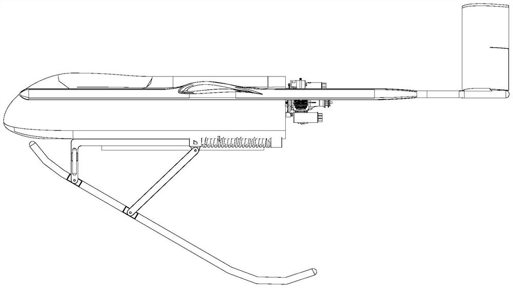
[0036] The difference from the above-mentioned embodiment is that the landing gear of a UAV provided in this embodiment includes a landing gear body 1, which is shock-absorbed after being folded / compressed, and the landing gear body 1 is provided with There is an energy storage device, and the energy storage device is charged after the landing gear body 1 is folded / compressed, and the energy storage device is used to provide power when the landing gear body 1 is deployed; the landing gear body 1 is provided with an airbag, so The folding / compressing distance of the landing gear body 1 provides space for the deployment of the airbag. In this embodiment, the landing gear body 1 is combined with the airbag. When the UAV fails to land, the folding / compression distance between the connecting frame 11 and the contact frame 12 can provide space for the expansion of the airbag, ensuring At touchdown, the airbags are fully deployed.

[0037] The landing gear body 1 includes a connecti...

Embodiment 3

[0043] Based on the first and second embodiments above, this embodiment provides a fall-resistant energy storage method for the landing gear of a drone. The specific method is as follows:

[0044] Landing in normal state: After the landing gear body 1 touches the ground, the propeller of the UAV is powered off, and the landing gear body 1 starts to fold / compress. During the folding / compression process, the deformation energy of the landing gear body 1 is stored; at the same time The exhaust gas discharged from the engine of the UAV is compressed by the compressor and filled into the gas cylinder 3 provided on the landing gear body 1 for storage; when the UAV takes off, the energy and gas stored in the folding / compression of the landing gear body 1 The gas stored in the bottle 3 is released together to provide power assist for the take-off of the UAV; the energy released by the spring 14 and the energy released by the gas bottle 3 are respectively located at the front end and th...


PUM


Abstract

The invention relates to an unmanned aerial vehicle undercarriage and an anti-falling energy storage method. The unmanned aerial vehicle undercarriage comprises an undercarriage body, the undercarriage body is damped after being folded / compressed, an energy storage device is arranged on the undercarriage body, the energy storage device is charged after the undercarriage body is folded / compressed, and the energy storage device is used for providing power when the undercarriage body is unfolded. The purpose of the invention is to provide buffering in a landing stage and store energy by adopting an energy storage device, convert gravitational potential energy of the unmanned aerial vehicle in the landing stage into elastic potential energy and store the elastic potential energy, and release the stored energy during takeoff, so that the elastic potential energy is converted into upward kinetic energy, thereby facilitating vertical takeoff of the unmanned aerial vehicle. Power consumption in the takeoff stage and electric energy in the descending stage are reduced.

Description

technical field [0001] The invention belongs to the technical field of unmanned aerial vehicles, and in particular relates to an unmanned aerial vehicle landing gear and an anti-drop energy storage method. Background technique [0002] Unmanned aerial vehicles are referred to as UAVs for short. UAVs can be divided into taxiing takeoff and landing and vertical takeoff and landing according to the takeoff mode. The landing gear of domestic vertical take-off and landing drones mostly uses skid-type landing gear with two poles on both sides or four pillars as the landing gear. These common structures can basically meet the take-off and landing performance requirements of small vertical take-off and landing drones, but there is a single structure , poor cushioning performance, poor stability, and can not protect the UAV in special circumstances during landing; compound wing vertical take-off and landing UAVs have a large take-off weight, and have high requirements for the load-ca...

Claims


Application Information

Patent Timeline
Patent Type & Authority Applications(China)
IPC IPC(8): B64D27/24B64D27/02B64C25/10B64C25/58B64C25/62
CPCY02T10/62Y02T50/60
Inventor 孔维良居婷陈全龙刘丹
Owner 重庆交通大学绿色航空技术研究院
Why Eureka
Try Eureka