Circulating type centrifugal oil washing machine

A kind of oil washing machine and circulation technology, which is applied in the field of circulating centrifugal oil washing machine, can solve the problems such as difficult inflow, achieve the effect of easy handling, easy collection, and guaranteed fluidity

Pending Publication Date: 2022-04-05
嘉兴闻军智能科技股份有限公司
View PDF15 Cites 0 Cited by
  • Summary
  • Abstract
  • Description
  • Claims
  • Application Information

AI Technical Summary

Problems solved by technology

[0002] Centrifugal oil washing machine is also called centrifugal deoiling machine. Its principle is that the motor drives the centrifugal barrel to rotate, and the centrifugal force generated when the centrifugal barrel rotates will throw out the oil on the objects in the barrel to achieve the deoiling effect. The oil thrown out is It slides down along the outer casing and flows into the bottom of the centrifugal oil washing machine. However, when the existing centrifugal oil washing machine is in use, it is found that when the temperature of the oil on the object is high, the fluidity of the oil is relatively strong and it is easy to flow along the outer casing. However, when the oil temperature is low, it is difficult to flow into the bottom of the oil machine

Method used


Image

  • Circulating type centrifugal oil washing machine
  • Circulating type centrifugal oil washing machine
  • Circulating type centrifugal oil washing machine

Examples


Embodiment Construction

[0021] The present invention is described in further detail below:

[0022] For details, see Figure 1 to Figure 3 :

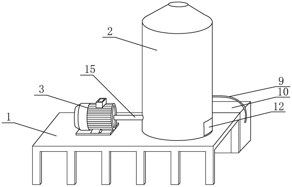
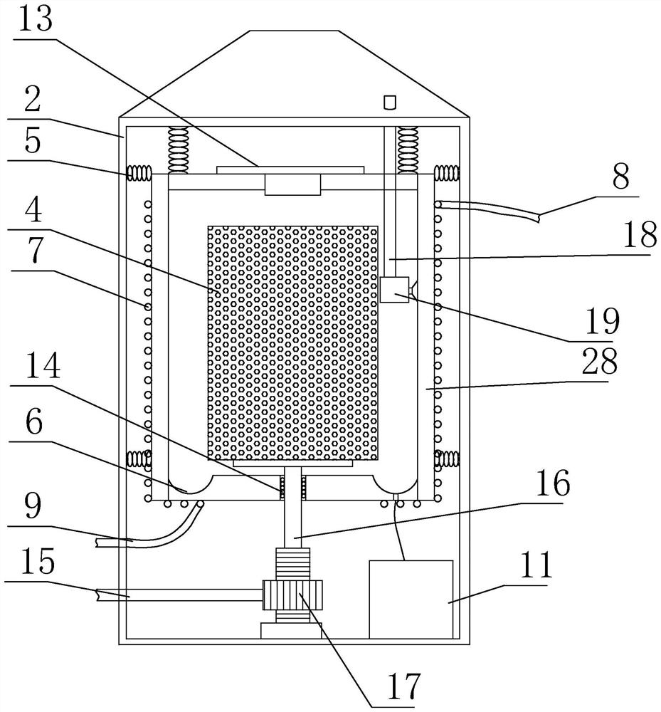
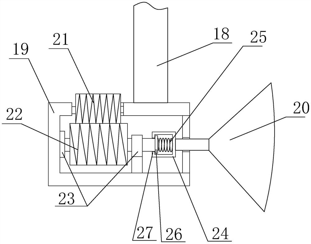
[0023] A circulating centrifugal oil washing machine, comprising a frame 1, an oil pan shell 2 arranged on the frame 1, a motor 3 arranged on one side of the oil pan shell 2, and a centrifugal barrel located inside the oil pan shell 2 4 and the transmission mechanism for connecting the output shaft of the motor 3 to the centrifugal barrel 4, and also includes an oil retaining barrel 28 arranged outside the centrifugal barrel 4 and a heating mechanism capable of heating the oil retaining barrel 28, the oil retaining barrel 28 Set concentrically with centrifugal barrel 4, the periphery of oil retaining barrel 28 is fixed on the inner wall of pan shell 2 by several extension springs 5, and is provided with discharge port at the upper end of oil retaining barrel 28, the bottom of oil retaining barrel 28 A mounting hole for the transmission mechanism to pass thro...


PUM


Abstract

The invention aims to provide the circulating type centrifugal oil washing machine which is provided with the heating device, so that the temperature of thrown-out oil can be kept, the fluidity of the oil is ensured, and the oil is collected and treated. Comprising a rack, an oil washing barrel shell, a motor, a centrifugal barrel and a transmission mechanism, and further comprises an oil blocking barrel and a heating mechanism, the periphery of the oil blocking barrel is fixed to the inner wall of the oil washing barrel shell through a plurality of tension springs, a discharging opening is formed in the upper end of the oil blocking barrel, and a mounting hole allowing the transmission mechanism to penetrate through is formed in the bottom of the oil blocking barrel; the heating mechanism comprises a spiral coil pipe, a liquid inlet pipe, a liquid outlet pipe, a heating pump and heat conduction oil, the spiral coil pipe is tightly attached to the outer wall of the oil blocking barrel, the upper end of the spiral coil pipe is connected with the liquid inlet pipe, the lower end of the spiral coil pipe is connected with the liquid outlet pipe, and the liquid inlet pipe and the liquid outlet pipe are connected with the output end and the input end of the heating pump respectively; the spiral coil pipe, the liquid inlet pipe and the liquid outlet pipe are filled with heat conduction oil.

Description

technical field [0001] The invention relates to the technical field of oil washing machines, in particular to a circulating centrifugal oil washing machine. Background technique [0002] Centrifugal oil washing machine is also called centrifugal deoiling machine. Its principle is that the motor drives the centrifugal barrel to rotate, and the centrifugal force generated when the centrifugal barrel rotates will throw out the oil on the objects in the barrel to achieve the deoiling effect. The oil thrown out is It slides down along the outer casing and flows into the bottom of the centrifugal oil washing machine. However, when the existing centrifugal oil washing machine is in use, it is found that when the temperature of the oil on the object is high, the fluidity of the oil is relatively strong and it is easy to flow along the outer casing. However, when the oil temperature is low, it is difficult to flow into the bottom of the oil machine. Contents of the invention [00...

Claims


Application Information

Patent Timeline
Patent Type & Authority Applications(China)
IPC IPC(8): B04B11/06B04B9/08B04B15/00B04B11/08
Inventor 谈闻军
Owner 嘉兴闻军智能科技股份有限公司
Why Eureka
Try Eureka