
Injection molding machine with material conveying function

A material transmission and injection molding machine technology, which is applied in the filtration of dispersed particles, separation of dispersed particles, chemical instruments and methods, etc., can solve the problems of difficult to ensure product quality, difficult to control the number and position of air bubbles, product hollowing, etc., to ensure product quality. Quality, reduce the time required, improve the effect of product quality

Inactive Publication Date: 2022-04-05
王晓新
View PDF1 Cites 0 Cited by
  • Summary
  • Abstract
  • Description
  • Claims
  • Application Information

AI Technical Summary

Problems solved by technology

[0004] However, when the device is in use, when the air generated by the pressurized cylinder is mixed into the molten plastic, it is difficult to control the number and position of the air bubbles after the air is converted into air bubbles, which may easily cause hollowing of the product and make it difficult to guarantee product quality.

Method used


Image

  • Injection molding machine with material conveying function
  • Injection molding machine with material conveying function
  • Injection molding machine with material conveying function

Examples


Embodiment 1

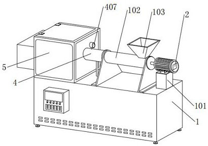
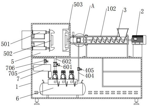
[0045] An injection molding machine with a material transmission function, comprising a box body 1, the upper end of the box body 1 is a working table, the front is an operating position, the top right side of the box body 1 is fixed with a motor bracket 101, and the top of the motor bracket 101 is equipped with a servo The motor 2, the casing 102 is fixedly installed in the middle position of the top of the box body 1, the top right side of the casing 102 is fixedly connected with the feed hopper 103, the inside of the casing 102 is embedded with an auger 3, and the left side of the casing 102 A heating bush 4 is fixedly connected through a flange, and a dustproof box 5 is fixed on the left side of the top of the box body 1;

[0046] Two pairs of hydraulic cylinders 501 are fixedly installed on the inner left side wall of the dustproof box 5, and a movable mold 502 is installed on one side of the hydraulic cylinder 501, and a fixed mold 503 is fixedly installed on the inner ri...

Embodiment 2

[0051] The difference between this embodiment and Embodiment 1 is: one end of the auger 3 is fixedly connected to the output end of the servo motor 2, the auger 3 and the bushing 102 are rotationally connected through a sealed bearing, and the end of the auger 3 is far away from the servo motor 2 provided with a circular opening;

[0052]One end of the heating rod 401 is embedded in the inside of the auger 3, and the heating rod 401 is closely attached to the auger 3;

[0053] The casing 102 communicates with the heating bush 4;

[0054] The auger 3 is sleeved on the outside of the heating rod 401. The auger 3 can fully exchange heat with the heating rod 401. The heating rod 401 conducts heat to the auger 3, and the raw material is heated by the auger 3 and its outer spiral blades. Preheating to increase the temperature of the raw material, and make the raw material heated evenly through the extrusion force of the auger 3 on the raw material;

[0055] The auger 3 transports ...


PUM


Abstract

The invention provides an injection molding machine with a material conveying function, which is characterized in that a heating rod is embedded in a heating bushing, the heating rod and the heating bushing are concentrically mounted, two supporting legs are fixedly mounted at one end of the heating rod, and the other ends of the supporting legs are fixed on the inner wall of the heating bushing; the design that the heating rod is embedded into the auger is adopted, raw materials are conveyed while being mixed through the force of the auger for extruding and shearing the raw materials, meanwhile, the auger and the spiral blades on the outer side of the auger are used for fully exchanging heat with the raw materials, the raw materials are rapidly heated to be in a plasticized state, and therefore the conditions of uneven mixing and uneven heating of the raw materials are avoided; the condition of raw material condensation is effectively improved, the time for heating the raw materials is shortened, and the overall production efficiency of the device is improved.

Description

technical field [0001] The invention relates to the technical field of injection molding production, in particular to an injection molding machine with material transmission function. Background technique [0002] Injection molding is a method of manufacturing industrial products. By injecting plastic materials in a molten state into the mold, after cooling, the plastic materials can be solidified and shaped to obtain finished products. Injection molding production is highly automated, with fast production speed, high efficiency and production efficiency. The characteristics of high precision are mainly used in the production of rubber products and plastic products; [0003] At present, the injection molding equipment on the market is usually installed after the feeding equipment, so the injection molding equipment usually has the function of material transmission. For example, an injection molding machine with the current patent application number of CN201810375328. The ai...

Claims


Application Information

Patent Timeline
Patent Type & Authority Applications(China)
IPC IPC(8): B29C45/47B29C45/46B29C45/63B29C45/74B29C45/17B29C45/76B01D46/24B01D53/26B01D53/28
Inventor 王晓新
Owner 王晓新
Learn More