Production equipment for multi-material-weight and multi-specification glass bottles
A glass bottle, multi-specification technology, applied in glass production, glass molding, glass manufacturing equipment, etc., can solve problems such as efficiency loss and material waste, and achieve the effect of saving mold costs
- Summary
- Abstract
- Description
- Claims
- Application Information
AI Technical Summary
Problems solved by technology
Method used
Image
Examples
Embodiment 1
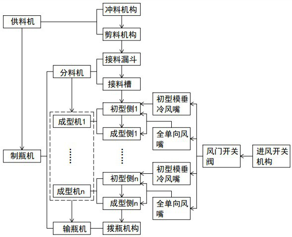
[0052] Such as figure 1 As shown, the production equipment of multi-material, heavy and multi-standard glass bottles is the same as the prior art, including a feeding machine and a bottle making machine, and the feed drops output by the feeding machine are sent into the bottle making machine to produce glass bottles. The feeding machine includes a punching mechanism and a shearing mechanism. The molten glass material is sent into the bottle making machine after passing through the punching mechanism and the shearing mechanism. The positional relationship between the punching mechanism and the shearing mechanism is well known in the art. Common sense, not repeat them here.
[0053] The bottle making machine includes a distributing machine, a forming machine and a bottle conveying machine, wherein the distributing machine includes a receiving hopper and a receiving trough, and the glass gob output from the shearing mechanism falls on the surface of the receiving trough after pas...
Embodiment 2
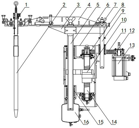
[0102] Such as Figure 18 As shown, the difference between this embodiment and Embodiment 1 is: the length of the air supply plate 24 is further increased, and four funnels 25 are arranged side by side in the air supply plate 24, and the inner air pipe 26 is connected with the inside of the air supply plate 24 at the same time. Four funnels 25 are communicated, have realized many drops of material. It is also possible to place more funnels 25 inside the gas supply plate 24 as required.
Embodiment 3
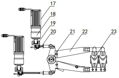
[0104] The difference between this embodiment and Embodiment 1 lies in that the structure of the cutting mechanism is different. Such as Figure 19 As shown, in this embodiment, the shearing mechanism includes a shearing servo motor 17, the motor shaft of the shearing servo motor 17 is connected to the input end of the shearing reducer 18, and the output end of the shearing reducer 18 is passed through the eccentric The drive sleeve 19 fixes one end of the shearing link 20, and the other end of the shearing link 20 is hinged to the middle of one of the two scissor arms 22, and one end of the two scissor arms 22 is respectively provided with a shearing gear 105, two cutting gears 105 mesh. Scissor blades 23 are respectively fixed at the ends of the other ends of the two scissor arms 22 , and the edges of the scissor blades 23 of the two scissor arms 22 are arranged oppositely.
[0105] When the shearing servo motor 17 is in action, the shearing link 20 is driven to reciprocat...
PUM
 Abstract
Description
Claims
Application Information
 - R&D
- Intellectual Property
- Life Sciences
- Materials
- Tech Scout
- Unparalleled Data Quality
- Higher Quality Content
- 60% Fewer Hallucinations
Browse by: Latest US Patents, China's latest patents, Technical Efficacy Thesaurus, Application Domain, Technology Topic, Popular Technical Reports.
© 2025 PatSnap. All rights reserved.Legal|Privacy policy|Modern Slavery Act Transparency Statement|Sitemap|About US| Contact US: help@patsnap.com


