Discharging device of carbonization furnace

A technology of discharging device and carbonization furnace, which is applied in the direction of discharging device, coke oven, petroleum industry, etc., can solve the problems of material accumulation, affecting the thermal cycle of furnace body, etc., and achieve the effect of easy maintenance and maintenance.

Pending Publication Date: 2022-04-05
宁夏亘瑞宏建筑安装有限公司
View PDF0 Cites 0 Cited by
  • Summary
  • Abstract
  • Description
  • Claims
  • Application Information

AI Technical Summary

Problems solved by technology

[0002] The current carbonization furnace mostly adopts a rotary furnace, and the rotary furnace is set with an inclination angle. During the production process, gravity is used to discharge materials at a low position. The internal heating type carbonization furnace often needs to be connected to an incinerator at the low position to pr

Method used


Image

  • Discharging device of carbonization furnace
  • Discharging device of carbonization furnace
  • Discharging device of carbonization furnace

Examples


Embodiment Construction

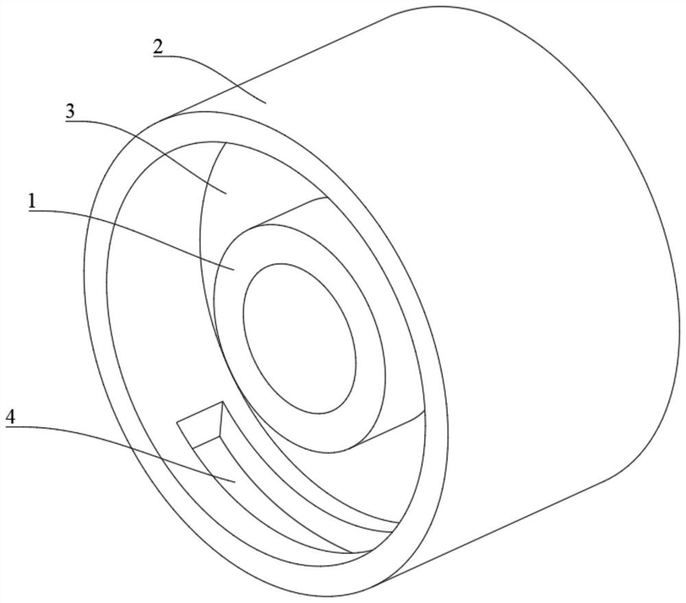
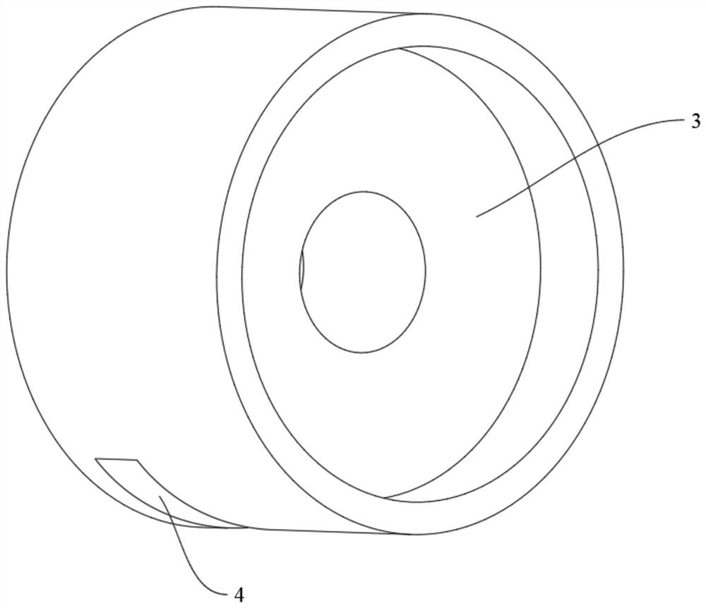
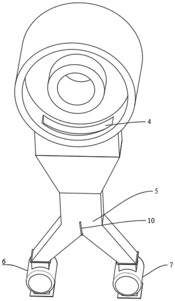
[0019] A discharge device for a carbonization furnace 12, comprising a cylinder with a double-layer structure connected to the carbonization furnace 12, a retaining ring 3 is arranged between the inner cylinder wall 1 and the outer cylinder wall 2; the outer cylinder wall 2 is provided with a discharge Port 4, the discharge port 4 is connected to the star unloader. The discharge device is sealed and connected with the carbonization furnace 12 and can rotate relatively. Wherein the discharging device is fixed, and the carbonization furnace 12 rotates.

[0020] The outer cylinder wall 2 is composed of carbon steel outer wall, thermal insulation rock wool and refractory bricks from outside to inside; the outer cylinder wall 2 and retaining ring 3 are made of refractory bricks.

[0021] The retaining ring 3 is set in the middle of the cylinder body, the inner cylinder wall 1 is extended on one side close to the carbonization furnace 12 to be flush with the outer cylinder wall 2, ...


PUM


Abstract

The invention belongs to the field of carbonization equipment, and particularly relates to a discharging device of a carbonization furnace. Comprising a double-layer barrel communicated with a carbonization furnace, and a check ring is arranged between an inner-layer barrel wall and an outer-layer barrel wall; and a discharge hole is formed in the outer-layer cylinder wall and is connected with a star-shaped unloader. The check ring is arranged in the middle of the barrel, one side, close to the carbonization furnace, of the inner-layer barrel wall extends out to be flush with the outer-layer barrel wall, the other side of the inner-layer barrel wall is flush with the check ring, and the discharge port is formed in the side, close to the carbonization furnace, of the inner-layer barrel wall. When the carbonization furnace is connected with the discharging device, the carbonization furnace is embedded between the outer-layer cylinder wall and the inner-layer cylinder wall and attached to the inner wall of the outer-layer cylinder wall, and materials slide to the position between the outer-layer cylinder wall and the inner-layer cylinder wall along the carbonization furnace cylinder and are discharged from the discharging port.

Description

technical field [0001] The invention belongs to the field of carbonization equipment, and in particular relates to a discharge device for a carbonization furnace. Background technique [0002] The current carbonization furnace mostly adopts a rotary furnace, and the rotary furnace is set with an inclination angle. During the production process, gravity is used to discharge materials at a low position. The internal heating type carbonization furnace often needs to be connected to an incinerator at the low position to provide heat for the carbonization furnace. Therefore, the discharge port is set at At the joint between the incinerator body and the carbonization furnace, if the discharge is not smooth enough, the material will accumulate at the incinerator mouth, which will affect the thermal cycle in the furnace body. Contents of the invention [0003] In order to solve the above problems, the present invention provides a carbonization furnace discharge device, the present...

Claims


Application Information

Patent Timeline
IPC IPC(8): C10B33/00
Inventor 胡建军雍波胡家荣
Owner 宁夏亘瑞宏建筑安装有限公司
Why Eureka
Try Eureka