
Bladeless flow-increasing environment-friendly fan

A booster fan and fan technology, applied in mechanical equipment, machine/engine, liquid fuel engine, etc., can solve the problems of wind energy loss, increase factory pressure, affect factory revenue, etc., achieve simple appearance and structure, increase air volume, The effect of high velocity

Pending Publication Date: 2022-04-05
江西威力固智能设备有限公司
View PDF0 Cites 0 Cited by
  • Summary
  • Abstract
  • Description
  • Claims
  • Application Information

AI Technical Summary

Problems solved by technology

[0002] At present, many high-power fans are used in the exhaust gas treatment system of the factory. Even if the exhaust gas is discharged intensively, the exhaust gas treatment effect is not good.
The main reason is that the exhaust gas needs to be conducted from the air source to the roof for treatment and discharge, resulting in too long ventilation pipes, and the flow velocity in the pipes is affected by the length of the pipes, resulting in a certain degree of loss of wind energy; in order to make up for the above wind energy loss , the factory has no choice but to choose a high-power fan to meet the exhaust gas transportation in the pipeline. Therefore, the fan accounts for most of the energy consumption in the entire factory exhaust gas treatment system, which invisibly increases the pressure on the factory's electricity cost, and not only affects The factory's revenue does not comply with the national energy conservation policy

Method used


Image

  • Bladeless flow-increasing environment-friendly fan
  • Bladeless flow-increasing environment-friendly fan
  • Bladeless flow-increasing environment-friendly fan

Examples


Embodiment Construction

[0031] In order to make the purpose, technical solutions and advantages of the embodiments of the present invention clearer, the technical solutions in the embodiments of the present invention will be clearly and completely described below in conjunction with the drawings in the embodiments of the present invention. Obviously, the described embodiments It is a part of embodiments of the present invention, but not all embodiments. The components of the embodiments of the invention generally described and illustrated in the figures herein may be arranged and designed in a variety of different configurations.

[0032] Accordingly, the following detailed description of the embodiments of the invention provided in the accompanying drawings is not intended to limit the scope of the claimed invention, but merely represents selected embodiments of the invention. Based on the embodiments of the present invention, all other embodiments obtained by persons of ordinary skill in the art wi...


PUM


Abstract

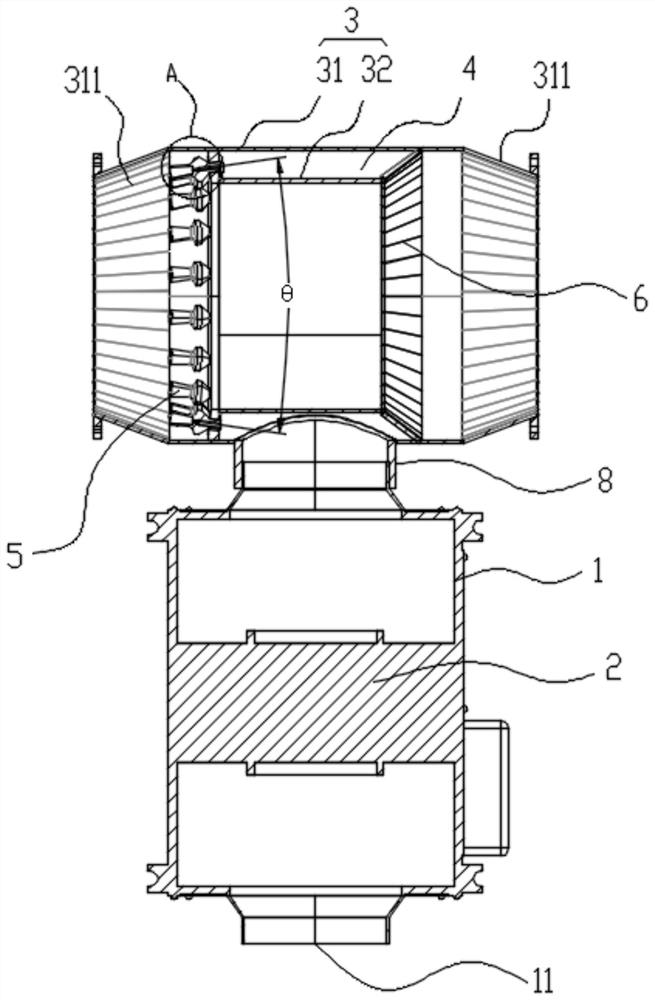
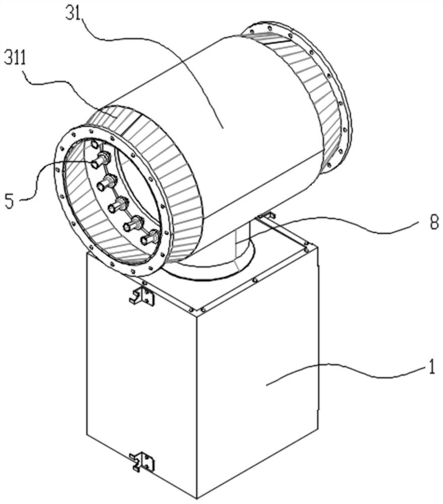
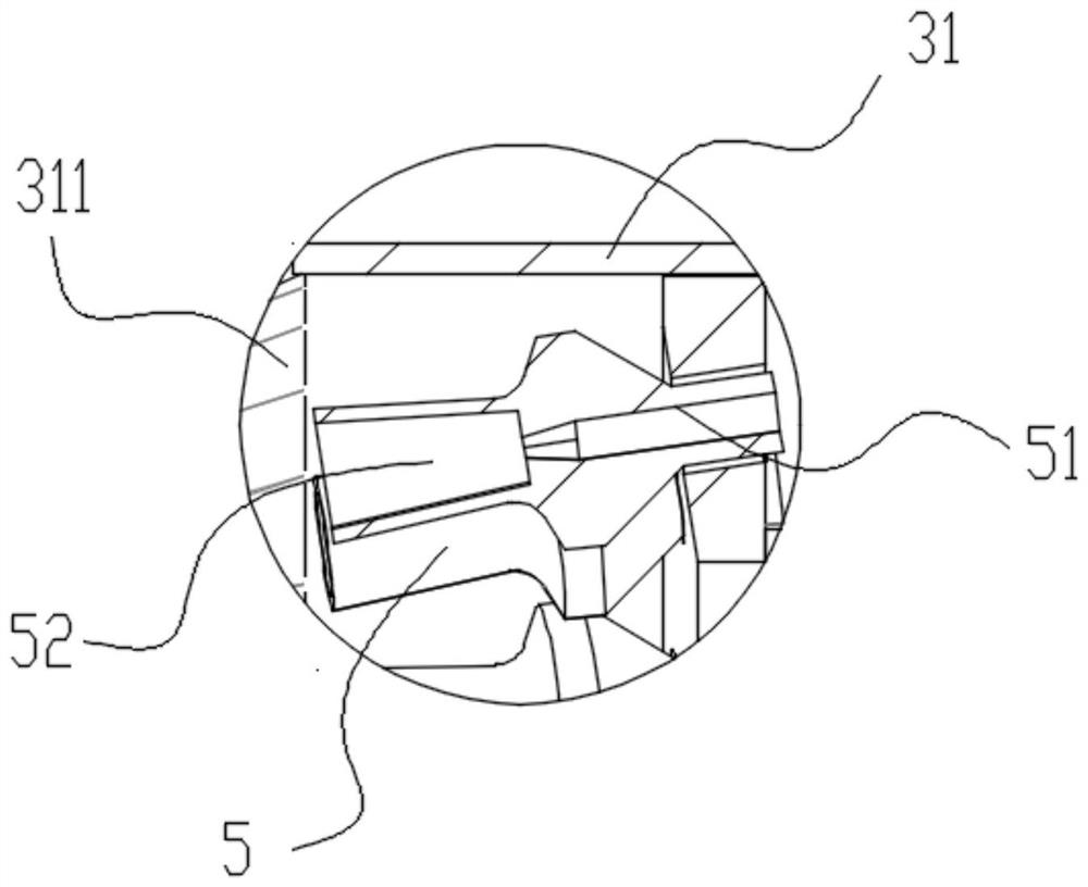
The invention relates to the field of environment-friendly devices, in particular to a bladeless flow-increasing environment-friendly fan which comprises a mute pipeline with an air inlet, a booster fan and a fan main weldment. The fan total weldment comprises an outer cylinder and an inner cylinder sleeved with the outer cylinder, and the outer cylinder and the inner cylinder are welded to form a hollow part to form a closed circular ring used for storing wind energy; taper pipes are arranged at the two ends of the outer cylinder. A plurality of mixed flow nozzles are arranged on the outer edge of the inner cylinder and close to the output channel; an air outlet of the mixed flow nozzle is downwards inclined along the central axis of the inner barrel and forms a preset angle; a rear wing guide cylinder is arranged at one end, far away from the mixed flow nozzle, in the mixed flow nozzle; and one end of the mixed flow nozzle is communicated with the closed circular ring. The bladeless flow-increasing environment-friendly fan has the characteristics of low energy consumption and high flow speed, is applied to a waste gas treatment system of a factory, and can meet the waste gas transportation efficiency of the factory while reducing the operation number of high-power fans.

Description

technical field [0001] The invention relates to the field of environmental protection devices, in particular to a bladeless fan for increasing flow and environmental protection. Background technique [0002] At present, many high-power fans are used in the exhaust gas treatment system of the factory. Even if the exhaust gas is discharged intensively, the exhaust gas treatment effect is not good. The main reason is that the exhaust gas needs to be conducted from the air source to the roof for treatment and discharge, resulting in too long ventilation pipes, and the flow velocity in the pipes is affected by the length of the pipes, resulting in a certain degree of loss of wind energy; in order to make up for the above wind energy loss , the factory has no choice but to choose a high-power fan to meet the exhaust gas transportation in the pipeline. Therefore, the fan accounts for most of the energy consumption in the entire factory exhaust gas treatment system, which invisibly ...

Claims


Application Information

Patent Timeline
IPC IPC(8): F04D25/08F04D29/00F04D29/42F04D29/44
Inventor 蔡志浩林利兰赵喜华刘威黄家全
Owner 江西威力固智能设备有限公司
Learn More