Full-automatic wire rod processing equipment

A kind of processing equipment and fully automatic technology, which is applied in the direction of assembly/disassembly of contact parts, etc., can solve the problems of increasing the production cost of jigs, small spacing between multiple core wires, and high difficulty of crimping terminals, and achieves integration of processing and testing, The effect of improving quality and ingenious structural design

Pending Publication Date: 2022-04-05
东莞市锐华自动化设备有限公司
View PDF1 Cites 0 Cited by
  • Summary
  • Abstract
  • Description
  • Claims
  • Application Information

AI Technical Summary

Problems solved by technology

[0002] Both multi-core wires and flat cables have multiple core wires arranged at intervals, which are very commonly used in people's production and life. In order to meet industrial automation and standardization, it is often necessary to process the wires. At present, the most common method is to crimp terminals on the wires. , Insert the plastic shell, but due to the small distance between multiple core wires, it is difficult to crimp the terminal
[0003] Existing wire processing equipment, such as the automatic cable end insertion machine disclosed in Chinese patent ZL 201920908382.6, uses the disengagement mechanism to lift the carrier off the conveyor belt, and then completes the end of the core wire, and then the disengagement mechanism descends to The jig is sent back to the conveyor belt to realize the terminal of the wire, but in actual use, it is found that there are still many deficiencies in its own structure and performance. The length is different, and different jigs need to be replaced during processing to meet the processing requirements, and after the jig is replaced, the detachment mechanism also needs to be adjusted accordingly, resulting in increased jig production costs and cumbersome operation steps

Method used


Image

  • Full-automatic wire rod processing equipment
  • Full-automatic wire rod processing equipment
  • Full-automatic wire rod processing equipment

Examples


Embodiment Construction

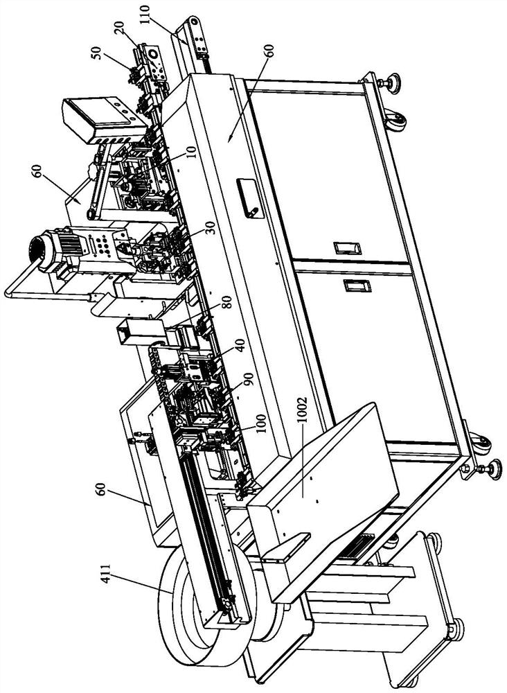
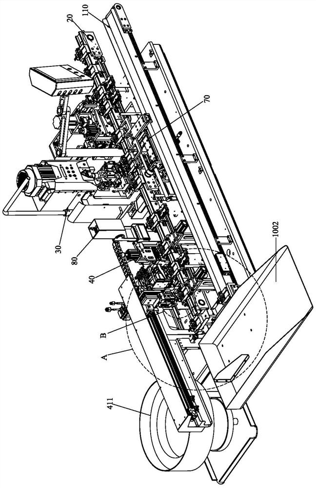
[0067] Please refer to Figure 1 to Figure 8 As shown, it shows the specific structure of the preferred embodiment of the present invention, including the combing wire stripping mechanism 10, the end mechanism 30 and the rubber shell mechanism 40, corresponding to the combing wire stripping mechanism 10, the end mechanism 30, The plastic shell mechanism 40 is respectively provided with a first station 101, a second station 301, and a third station 401; it also includes a conveying mechanism 20 for conveying wires to different stations, and the conveying mechanism 20 is provided with The wire clamping jig 50 , the conveying mechanism 20 drives the wire clamping jig 50 to transport to the corresponding station.

[0068] The combing wire stripping mechanism 10 is provided with a protective cover 60, and the combing wire stripping mechanism 10 includes a third Y-axis driving device 11, a combing device 12 and a cutting and peeling device arranged on the third Y-axis driving device...


PUM


Abstract

The invention discloses full-automatic wire processing equipment, which comprises a wire combing and stripping mechanism, a terminal crimping mechanism and a rubber shell inserting mechanism, and is characterized in that a first station, a second station and a third station are respectively arranged corresponding to the wire combing and stripping mechanism, the terminal crimping mechanism and the rubber shell inserting mechanism; the device further comprises a conveying mechanism, and a wire clamping jig is arranged on the conveying mechanism. The conveying mechanism comprises a first conveying device and a second conveying device; a terminal crimping feeding mechanism is arranged between the first conveying device and the second conveying device, the terminal crimping feeding mechanism comprises a feeding device and a carrying device, the second station is arranged on the feeding device, and the feeding device is provided with a first Y-axis driving device; the conveying device is provided with two conveying parts. The first Y-axis driving device is arranged to drive the wire clamping jigs to move front and back to be matched with core wires with different extending lengths, universality is good, the two carrying parts are arranged in a matched mode, the two wire clamping jigs are driven to conduct feeding and discharging at the same time, and working efficiency is high.

Description

technical field [0001] The invention relates to the technology in the field of wire processing equipment, in particular to a fully automatic wire processing equipment, which is mainly used for processing multi-core wires and cables. Background technique [0002] Both multi-core wires and flat cables have multiple core wires arranged at intervals, which are very commonly used in people's production and life. In order to meet industrial automation and standardization, it is often necessary to process the wires. At present, the most common method is to crimp terminals on the wires. , Insert the plastic shell, but due to the small distance between multiple core wires, it is difficult to crimp the terminal. [0003] Existing wire processing equipment, such as the automatic cable end insertion machine disclosed in Chinese patent ZL 201920908382.6, uses the disengagement mechanism to lift the carrier off the conveyor belt, and then completes the end of the core wire, and then the d...

Claims


Application Information

Patent Timeline
Patent Type & Authority Applications(China)
IPC IPC(8): H01R43/20
Inventor 谭乾永
Owner 东莞市锐华自动化设备有限公司
Why Eureka
Try Eureka