
Channel steel cutting device with scrap removing function

A cutting device and function technology, applied in the field of channel steel cutting devices, can solve the problems affecting the channel steel cutting accuracy, channel steel bias, inconvenient cleaning in the later stage, etc.

Pending Publication Date: 2022-04-08
TAICANG DEHAO FASTENER CO LTD
View PDF0 Cites 0 Cited by
  • Summary
  • Abstract
  • Description
  • Claims
  • Application Information

AI Technical Summary

Problems solved by technology

[0003] When the cutting device currently used for channel steel is in use, the cutting of channel steel will generate a large amount of debris, which splashes and falls on the base, which not only affects the use of the base, but also brings inconvenience to the later cleaning, and after the channel steel is cut , the workers are required to move the remaining channel steel forward to the bottom of the cutting machine, so as to continue cutting, and when the workers push the channel steel to move, it is easy to drive the channel steel to be biased, thus affecting the cutting accuracy of the channel steel. It should be noted that the above content Belonging to the technical cognition category of the inventor does not necessarily constitute prior art

Method used


Image

  • Channel steel cutting device with scrap removing function
  • Channel steel cutting device with scrap removing function
  • Channel steel cutting device with scrap removing function

Examples


Embodiment Construction

[0021] In order to explain the overall concept of the present invention more clearly, the following will be described in detail by way of examples in conjunction with the accompanying drawings.

[0022] In describing the present invention, it is to be understood that the terms "center", "upper", "lower", "front", "rear", "left", "right", "vertical", "horizontal", The orientation or positional relationship indicated by "top", "bottom", "inner", "outer", "axial", "radial" and "circumferential" are based on the orientation or positional relationship shown in the drawings, only It is for the convenience of describing the present invention and simplifying the description, but does not indicate or imply that the referred device or element must have a specific orientation, be constructed and operated in a specific orientation, and thus should not be construed as limiting the present invention.

[0023] In addition, the terms "first" and "second" are used for descriptive purposes only...


PUM


Abstract

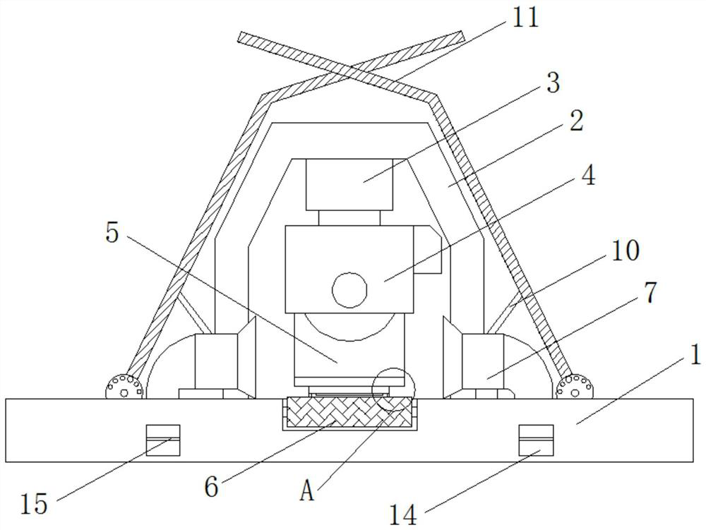
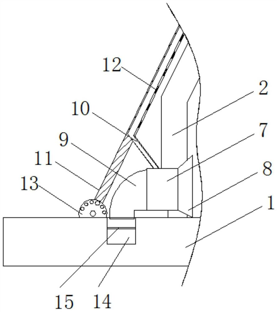
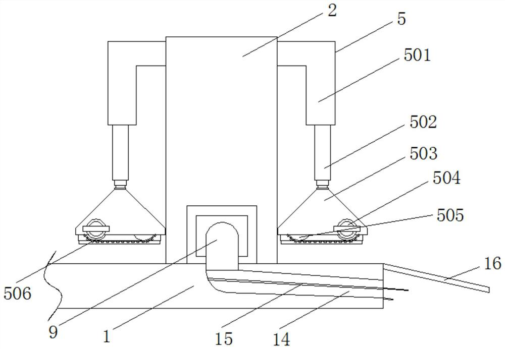
The channel steel cutting device with the scrap removing function comprises a base, a cutting device body is arranged at the top end of the base, adjusting seats are arranged at the positions, located on the two sides of the cutting device body, of the top end of the base, and a discharging groove is formed in the inner side of the base. By arranging a dust collector, a discharging groove, a filter plate and a dust suction pipe, the inclination angle of a protection plate is adjusted through an adjusting seat, splashing chippings can be conveniently intercepted by the protection plate, when channel steel is cut, the dust collector on the protection plate operates, the chippings generated by cutting are sucked into a dust discharging pipe through a dust suction cover and conveyed into the discharging groove, and the cutting efficiency of the channel steel is improved. And dust generated by cutting is absorbed through dust suction holes in the inner side of the protection plate, the absorbed dust enters a dust discharging pipe through a dust suction pipe on one side of the protection plate and then enters a discharging groove, chippings and the dust are filtered through a filtering plate and then flow out, chipping cleaning is completed, and the problem of cleaning of the chippings generated by channel steel cutting is effectively solved.

Description

technical field [0001] The invention belongs to the technical field of channel steel processing, in particular to a channel steel cutting device with chip cleaning function. Background technique [0002] Iron is the most used metal material. It has high strength, good mechanical properties, and low cost. It is suitable for large-scale production and is widely used in various fields of social production and life. The channel steel in steel has a grooved cross section. Type steel is often used in construction and mechanical fields, and the channel steel needs to be cut before use to obtain the required length. [0003] When the cutting device currently used for channel steel is in use, the cutting of channel steel will generate a large amount of debris, which splashes and falls on the base, which not only affects the use of the base, but also brings inconvenience to the later cleaning, and after the channel steel is cut , the workers are required to move the remaining channel...

Claims


Application Information

Patent Timeline
Patent Type & Authority Applications(China)
IPC IPC(8): B23D19/00B23Q11/08B23Q11/00B21D43/12B23Q7/08
Inventor 龚志浩
Owner TAICANG DEHAO FASTENER CO LTD
Learn More