
Electric power steering system control method and device based on input shaper

An electric power steering and input shaping technology, applied in automatic steering control components, electric steering mechanisms, steering mechanisms, etc., can solve problems such as large phase, phase lag, angle control overshoot, etc., to improve stability and comfort. , to ensure the effect of continuity

Active Publication Date: 2022-04-08
GUANGZHOU XIAOPENG CONNECTIVITY TECH CO LTD
View PDF9 Cites 0 Cited by
  • Summary
  • Abstract
  • Description
  • Claims
  • Application Information

AI Technical Summary

Problems solved by technology

[0002] EPS (Electric Power Steering, electric power steering system) in the related art utilizes steering wheel assist torque to carry out angle control, but EPS model and road model are difficult to model, adopt the non-model-based control method to carry out angle control more, for example, adopt PID ( Proportion Integration Differentiation, proportional-integral-differential) controller, active disturbance rejection controller and other controllers perform angle control, and overshoot and phase lag inevitably occur during the angle control process
In order to reduce the overshoot of the controller, the related technology reduces the gain of the controller and the observer, but this leads to a large phase lag in the angle tracking process
In order to solve the phase lag, the related technology adopts the preview strategy, utilizes the motion planning stitch (stitching point) strategy (the trajectory of the vehicle can be kept unchanged for a certain period of time in the planning process), and selects the curvature of the fixed future trajectory point for feedforward control, but overshoot of angle control
[0003] The EPS control in the related technology makes the EPS generate unnecessary jitter, reduces the stability of the EPS angle tracking, causes the vehicle angular acceleration to change rapidly, and reduces the comfort of the vehicle during automatic driving

Method used


Image

  • Electric power steering system control method and device based on input shaper
  • Electric power steering system control method and device based on input shaper
  • Electric power steering system control method and device based on input shaper

Examples


Embodiment Construction

[0037] Embodiments of the present application will be described in more detail below with reference to the accompanying drawings. Although embodiments of the present application are shown in the drawings, it should be understood that the present application may be embodied in various forms and should not be limited by the embodiments set forth herein. Rather, these embodiments are provided so that this application will be thorough and complete, and will fully convey the scope of this application to those skilled in the art.

[0038] The terminology used in this application is for the purpose of describing particular embodiments only, and is not intended to limit the application. As used in this application and the appended claims, the singular forms "a", "the", and "the" are intended to include the plural forms as well, unless the context clearly dictates otherwise. It should also be understood that the term "and / or" as used herein refers to and includes any and all possible ...


PUM


Abstract

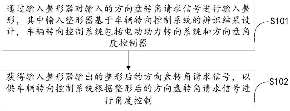
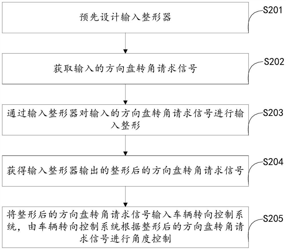
The invention relates to an electric power steering system control method and device based on an input shaper. The method comprises the steps that input shaping is conducted on an input steering wheel angle request signal through an input shaper, the input shaper is designed based on an identification result of a vehicle steering control system, and the vehicle steering control system comprises an electric power steering system and a steering wheel angle controller; and the reshaped steering wheel angle request signal output by the input reshaper is obtained so that the vehicle steering control system can conduct angle control according to the reshaped steering wheel angle request signal. According to the scheme provided by the invention, the jitter of the EPS in the angle tracking process can be reduced or even eliminated, the stability of EPS angle tracking is improved, and the comfort during automatic driving of the vehicle is improved.

Description

technical field [0001] The present application relates to the technical field of automatic driving, and in particular to a method and device for controlling an electric power steering system based on an input shaper. Background technique [0002] EPS (Electric Power Steering, electric power steering system) in the related art utilizes steering wheel assist torque to carry out angle control, but EPS model and road model are difficult to model, adopt the non-model-based control method to carry out angle control more, for example, adopt PID ( Proportion Integration Differentiation, proportional-integral-differential) controllers, active disturbance rejection controllers and other controllers perform angle control, and overshoot and phase lag inevitably occur during the angle control process. In the related art, in order to reduce the controller overshoot, the gains of the controller and the observer are reduced, but this leads to a large phase lag in the angle tracking process....

Claims


Application Information

Patent Timeline
Patent Type & Authority Applications(China)
IPC IPC(8): B62D6/00B62D5/04B62D113/00
CPCY02P90/02
Inventor 李想李弼超周磊张枫
Owner GUANGZHOU XIAOPENG CONNECTIVITY TECH CO LTD
Learn More