Wall painting device for building engineering construction

A technology of construction engineering and brush head, applied in the direction of construction, building structure, etc., can solve the problem of high cost of use, and achieve the effect of expanding the scope and improving the painting speed.

Pending Publication Date: 2022-04-08
徐州永硕精密机械科技有限公司
View PDF0 Cites 0 Cited by
  • Summary
  • Abstract
  • Description
  • Claims
  • Application Information

AI Technical Summary

Problems solved by technology

[0005] Aiming at the deficiencies of the prior art, the present invention provides a wall plastering device for building engineering construction, which has the advantages of reasonably changing the plastering size according to the size of the plastering surface, saving the use cost, and completing the plastering of the corners at one time, which solves the problem of only The painting speed can be changed by speeding up the painting frequency, the corners of the wall need to be painted on both sides, and two structures are needed to realize the rotation in the horizontal and vertical directions, resulting in high cost of use

Method used


Image

  • Wall painting device for building engineering construction
  • Wall painting device for building engineering construction
  • Wall painting device for building engineering construction

Examples


Embodiment 1

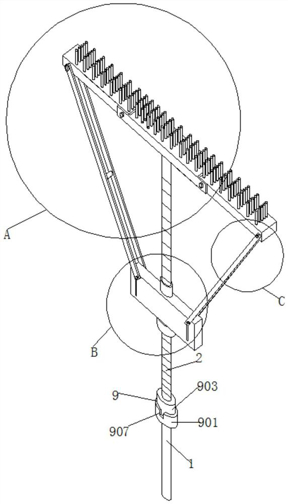
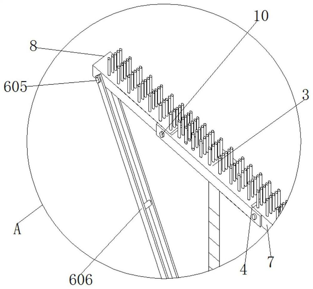
[0036] see figure 1 , 2, 3, 4, 9, 10, a wall painting device for building construction, including a handle and a brush head, the handle includes an upper half rod 2 and a lower half rod 1, an upper half rod 2 and a lower half A rod connection structure 9 is connected between the half rods 1. The brush head is composed of the middle brush head 3, the left brush head 8 and the right brush head 7. The left and right ends of the middle brush head 3 are provided with installation cutouts 4. The side brush head 8 and the right brush head 7 are divided into two installation cutouts 4 inside, and the front of the middle brush head 3 is provided with movable connecting pins 10, and one of the movable connecting pins 10 runs through the middle brush head 3 and the left brush head at the same time. Head 8, another movable connection pin 10 runs through the middle brush head 3 and the right side brush head 7 at the same time, the middle brush head 3 and the left side brush head 8 are art...

Embodiment 2

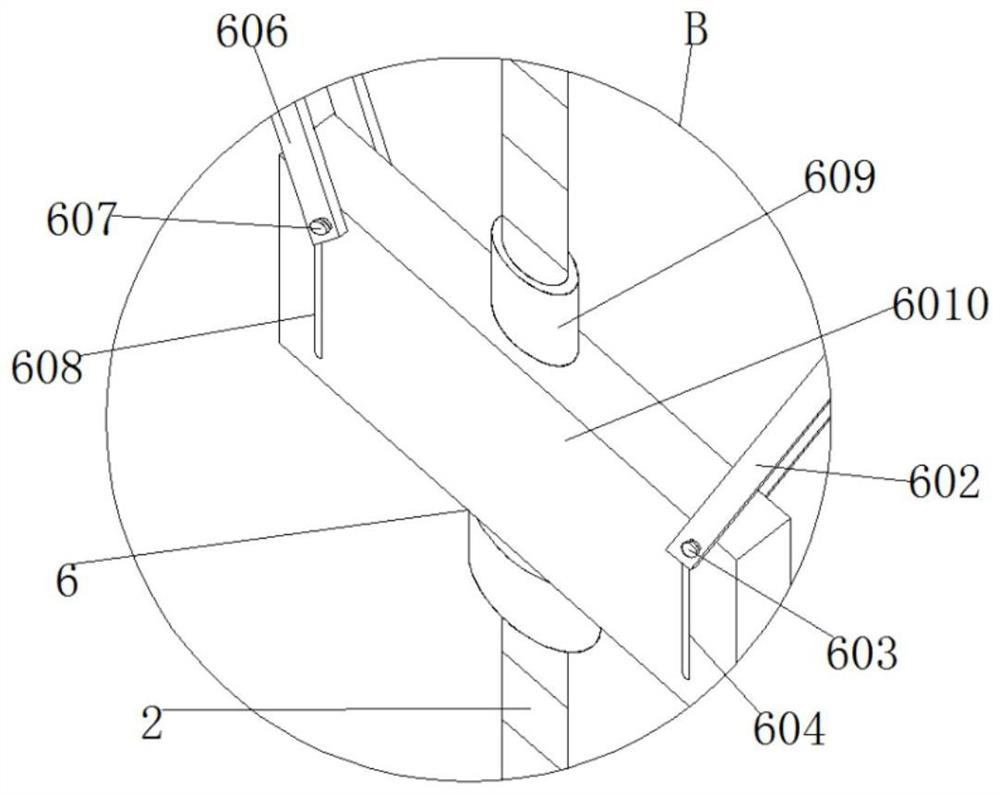
[0040] see figure 1 , 10 , the connecting cylinder 609 is I-shaped, the rectangular movable block 6010 is located in the middle part of the connecting cylinder 609, and the diameter of the inner wall of the rectangular movable block 6010 is smaller than the diameters of the top and bottom of the connecting cylinder 609.

[0041] Through the movable socket of the rectangular movable block 6010 and the connecting cylinder 609, when the connecting cylinder 609 rotates, the function of the rectangular movable block 6010 not turning, thereby avoiding breaking the left connecting rod 606 and the right connecting rod 602.

Embodiment 3

[0043] see figure 1 , 9 , the left connecting piece 607 is the same as the right connecting piece 603, and is composed of a fixed rod 11 and a fastening nut 5, the fixed rod 11 is composed of a stepped cylindrical rod and a threaded surface rod, and the stepped cylindrical rod and the fastening nut 5 Both are T-shaped with an included angle of 180 degrees, and the diameters of the stepped cylindrical rod and the solid part of the fastening nut 5 are the same.

[0044] By rotating the fastening nut 5 in the left connecting piece 607 so that its outer wall close to the rectangular movable block 6010 is located at the outside of the left side through hole 608, then the fixed rod 11 in the left connecting piece 607 is moved to the left side through hole 608 component of the rectangular hole, so that the left brush head 8 and the right brush head 7 are not mirror images of each other in the left and right directions,

[0045] By rotating the fastening nut 5 in the right connectin...


PUM


Abstract

The invention relates to the technical field of painting, and discloses a wall painting device for building engineering construction, which comprises a holding rod and a brush head. Therefore, the left brush head and the right brush head form a mirror image or cannot form a mirror image, so that the left brush head, the right brush head and the middle brush head form a brush, the left brush head and the middle brush head form a brush, and the right brush head and the middle brush head form a brush. A threaded cylinder is rotated to drive a left connecting rod and a right connecting rod to move up and down, the included angle between a left brush head or a right brush head and a middle brush head is driven to be 90 degrees, so that corners of a wall can be painted at a time, and rotation of the brush in the horizontal direction and the vertical direction can be achieved through one mechanism of an adjusting structure; therefore, the use cost is saved.

Description

technical field [0001] The invention relates to the technical field of plastering, in particular to a wall plastering device for building engineering construction. Background technique [0002] After the construction workers have built the basic building, it needs to be finely decorated in the later stage. Painting is one of them. The scope of painting includes the four sides and the roof. During the painting process, a painting device is required for painting. [0003] The brushes in the wall painting devices used for construction projects in the market are generally fixed, and cannot be reasonably arranged according to the actual painting area. When painting large and small areas, the painting speed can only be changed by accelerating the painting frequency. , and when painting the corner of the wall, it is necessary to paint the two walls once, and it needs to be painted twice to complete the painting of the corner, and when painting the top and the walls of the four volu...

Claims


Application Information

Patent Timeline
IPC IPC(8): E04F21/06E04F21/02
Inventor 赵正卯
Owner 徐州永硕精密机械科技有限公司
Why Eureka
Try Eureka