
Multi-dimensional measurement method for obtaining target form

A measurement method and target technology, applied in the direction of measuring devices, instruments, optical devices, etc., can solve the problems of large amount of points and calculation, difficulty in real-time measurement and application, and long calculation time, so as to improve the scope of application and physical hardware Effect of low complexity and improved measurement accuracy

Active Publication Date: 2022-04-08
云南特可科技有限公司
View PDF5 Cites 0 Cited by
  • Summary
  • Abstract
  • Description
  • Claims
  • Application Information

AI Technical Summary

Problems solved by technology

However, the existing intelligent measurement can only measure distance and two-dimensional area with a single camera device. When it is necessary to output object shape data or three-dimensional data, at least three camera devices are required to measure the measurement target from different angles. The required object shape data or three-dimensional data can only be formed after the mold
In particular, the existing technology often needs to rely on 3D point cloud technology and 3D modeling technology when obtaining object shape data. The amount of points collected and the amount of calculation of these two technologies are very large. Generally, a high-performance computer is required to complete it, and the device is complicated. And while the cost is high, due to the long calculation time, it is difficult to realize the application in the field of real-time measurement

Method used


Image

  • Multi-dimensional measurement method for obtaining target form
  • Multi-dimensional measurement method for obtaining target form
  • Multi-dimensional measurement method for obtaining target form

Examples


Embodiment 1

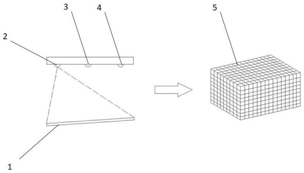
[0029] A multi-dimensional measurement method for obtaining target morphology, comprising:

[0030] S1. Perform matrix measurement on the bearing surface where the target to be measured is located by the measuring device, and convert the bearing surface where the target to be measured is located according to the conversion model to form a virtual background measurement space.

[0031] S2. Select a virtual measurement surface in the virtual background measurement space, and form correction parameters of each dot matrix on the bearing surface where the target to be measured is located relative to the virtual measurement surface.

[0032] S3. When it is recognized that the target to be measured appears on the bearing surface where the target to be measured is located, the target to be measured and the bearing surface where the target to be measured is located are measured in matrix by the measuring device, and according to the conversion model described in S1 and the correction pa...

Embodiment 2

[0045] Based on the multi-dimensional measurement method for obtaining the target form described in Embodiment 1, when anchoring the virtual target measurement space as a virtual space that coincides with each virtual dot matrix of the virtual background measurement space, first use the virtual target measurement space and the virtual background measurement space Among them, the overlapping part of the distance and angle of the original measurement point is the anchor point. The virtual measurement matrix point in the virtual target measurement space is compared with the virtual matrix point in the corresponding position in the virtual background measurement space. The point where the position error occurs is based on the virtual The matrix point position data corrects the point position data for the virtual measurement matrix point position data. After the correction of the position data of all virtual measurement matrix points is completed, it is determined that the action is...

Embodiment 3

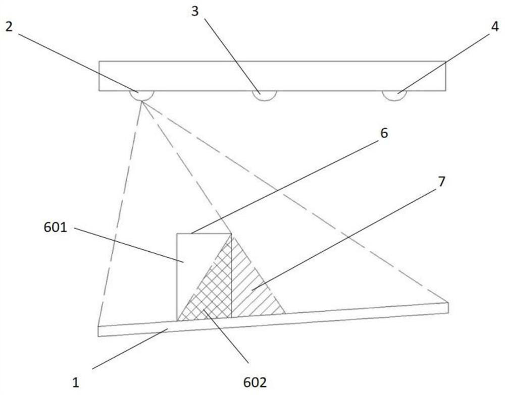
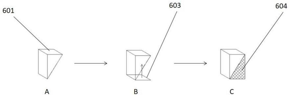
[0047] Based on the multi-dimensional measurement method for obtaining the shape of the target described in Embodiment 1, the method of filling the unmeasured surface of the measurement target with data according to the projection structure is as follows: first, in the virtual background measurement space, according to the acquired virtual measurement matrix point data A virtual form model-measuring surface of the measuring target facing the fast distance measuring device is formed. Then, according to the relative positional relationship between the projection device and the fast distance measuring device, the projection structure is adjusted to the position where the virtual shape model-measuring surface fits. Then the size of the projected structure is adjusted so that the projected structure overlaps with the virtual shape model-measuring surface to the greatest extent. Afterwards, data points are supplemented with the structural boundary of the projected structure in the f...


PUM


Abstract

In order to solve the problems existing in the prior art, the invention provides a multi-dimensional measurement method for obtaining a target form, and the method comprises the steps: S1, converting a bearing surface where a to-be-measured target is located into a virtual background measurement space through a measurement device and a conversion model; s2, selecting a virtual measurement surface in the virtual background measurement space, and forming correction parameters of each dot matrix of the bearing surface where the target to be measured is located relative to the virtual measurement surface. And S3, identifying the to-be-measured target, performing matrix measurement on the to-be-measured target and the bearing surface where the to-be-measured target is located through the measurement device, and converting the to-be-measured target and the bearing surface where the to-be-measured target is located to form a virtual target measurement space. And S4, comparing the virtual background measurement space with the virtual target measurement space to obtain a virtual form of the target to be measured in the virtual background measurement space and on the virtual measurement surface. And S5, outputting the measurement data of the to-be-measured target as required. According to the method disclosed by the invention, the precision error of the measured target form data is 0.04-0.6 cm, and the measurement and analysis time is prolonged to 0.01-0.001 second.

Description

technical field [0001] The invention relates to the field of intelligent measurement, in particular to a multi-dimensional measurement method for acquiring target shapes. Background technique [0002] Measurement is to use data to describe the observed phenomenon according to a certain law, that is, to make a quantitative description of things. The traditional measurement is to use a measuring device to physically measure the measurement target, and the measurement efficiency is low. In recent years, due to the continuous advancement of computer computing power and virtual model analysis technology, intelligent measurement of measurement targets based on image data acquired by cameras has become more and more measurement methods. However, the existing intelligent measurement can only measure distance and two-dimensional area with a single camera device. When it is necessary to output object shape data or three-dimensional data, at least three camera devices are required to ...

Claims


Application Information

Patent Timeline
Patent Type & Authority Applications(China)
IPC IPC(8): G01B11/24
Inventor 何宣余朱梦玺
Owner 云南特可科技有限公司
Learn More