
Cable peeling device and cable peeling method

A technology for cables and detection devices, which is applied in the field of cable peeling devices, and can solve problems such as inaccuracy and inconvenience

Pending Publication Date: 2022-04-08
CHINA ACADEMY OF INFORMATION & COMM
View PDF0 Cites 0 Cited by
  • Summary
  • Abstract
  • Description
  • Claims
  • Application Information

AI Technical Summary

Problems solved by technology

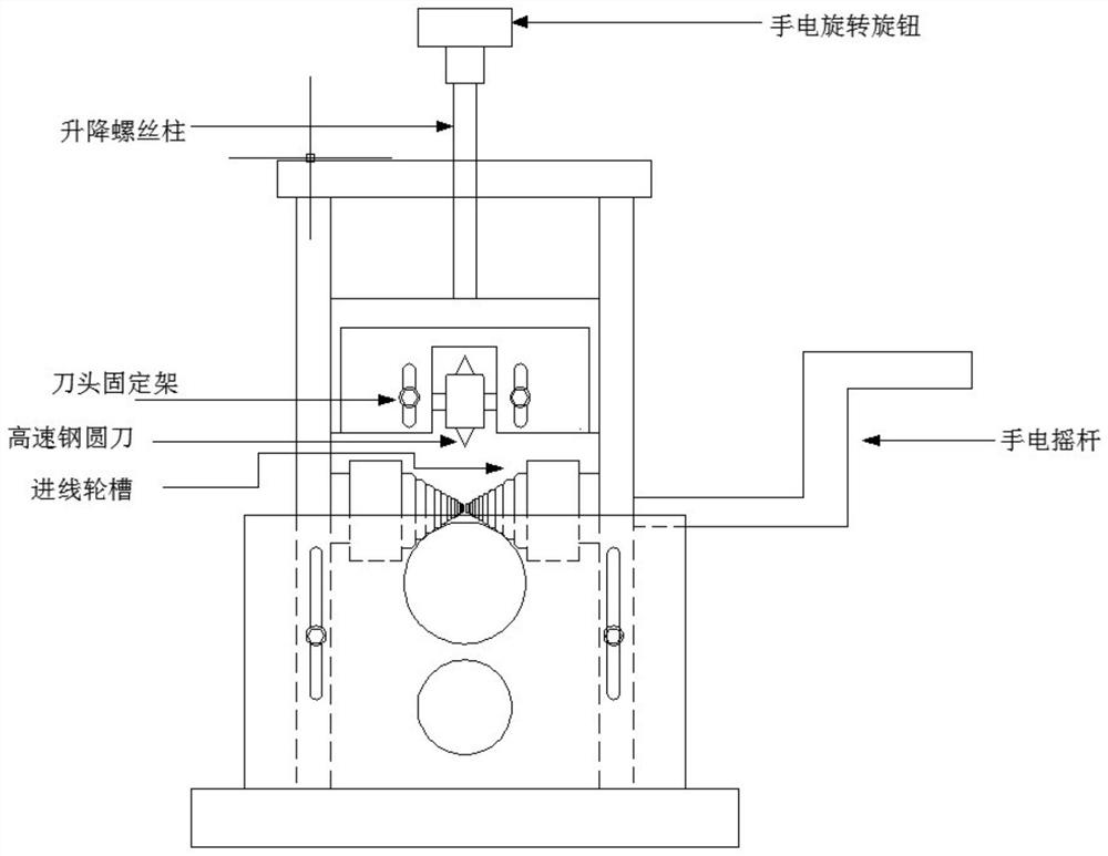
[0005] In the above-mentioned prior art, the positioning plate 8 that prevents the internal circuit of the cable from being damaged due to excessive cutting of the cable sheath by the cutter head 9 requires human judgment and control, which is inconvenient and inaccurate

Method used


Image

  • Cable peeling device and cable peeling method
  • Cable peeling device and cable peeling method
  • Cable peeling device and cable peeling method

Examples


no. 1 Embodiment

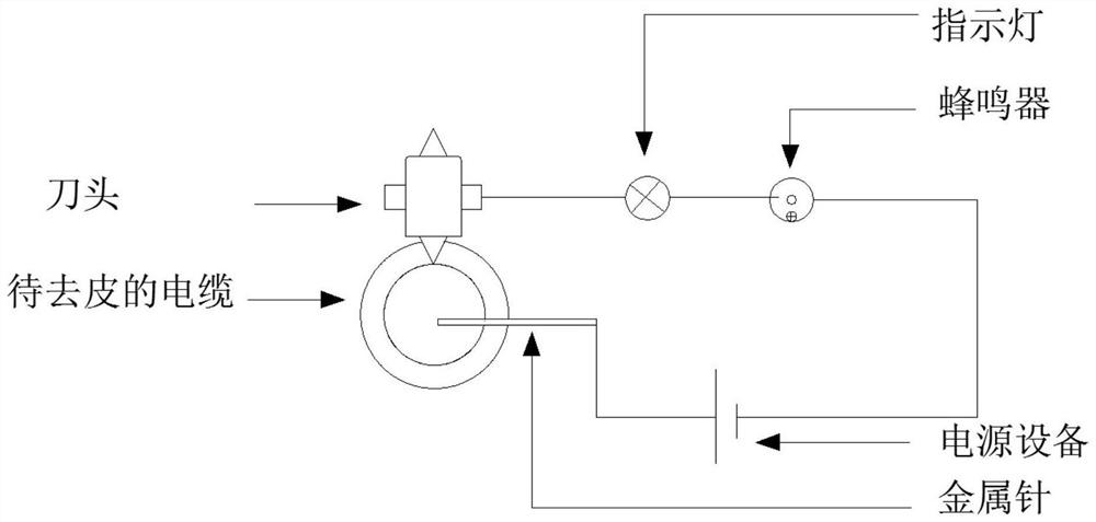
[0030] The present invention provides a cable peeling apparatus, a schematic diagram image 3 Distance

[0031] Includes cutters, indicators, buzzers and metal needles. One-end cutter head of the circuit and buzzer, the other end of the circuit connects a metal needle, insert the metal needle into the cable to be peeled to peeled, when the cutter is in the process of degeneration, the conductor of the cable, The entire circuit is turned on, the indicator is on, the buzzer issues an alarm sound, the relative movement of the cutter head and the conductor is immediately stopped, or the tip height is automatically adjusted, thereby avoiding the injury of the tool head to the conductor. When the head is adjusted to a safe distance from the distance from the conductor, the indicator and buzzer are not turned on, and the peeling device continues to work. The conductor of the cable is detected by a metal needle to control or adjust the peeling operation of the cutter head.

[0032] The adv...

no. 2 Embodiment

[0034] The present invention also provides a cable peeling apparatus, a schematic diagram Figure 4 Distance

[0035]Includes a cutter head, an eddy current sensor, an adjustment button, a single chip, a display. In order to prevent the tutoon in advance, the eddy current sensor probe can be installed in the head position, referred to as the eddy current sensor. The vortex flow sensor can be static or dynamically non-contact, high linearity, and high resolution measuring the distance from the surface of the probe. There is an advantage of long-term working stability, strong anti-interference ability, and response speed. It is very suitable for measuring the relative position of the tool head and the cable conductor when the cable is removed. Since the principle of the electric turbine sensor is to provide an alternating current to the coil in the probe, a magnetic field is formed around the sensor coil, and the conductor will be placed in this magnetic field, and the electrot can b...


PUM


Abstract

The invention provides cable peeling equipment, which is characterized in that an eddy current sensor is additionally arranged at the position of a tool bit, the eddy current sensor is used for measuring the relative position of the tool bit and a cable conductor when the cable is peeled, a display screen displays the distance between the tool bit and the cable conductor, and a single-chip microcomputer reads the distance between the tool bit and the conductor in real time. The safety distance between the tool bit and the conductor is input on the single-chip microcomputer according to requirements, the single-chip microcomputer compares the distance read in real time with the safety distance, the single-chip microcomputer controls the adjusting knob to adjust the height of the tool bit in real time, and when the tool bit deviates from the safety distance, the height of the tool bit is adjusted to be within the set safety distance range. According to the invention, on the basis of the existing peeling equipment, a tool bit to conductor distance monitoring facility is additionally arranged, so that the purpose of removing the sheath without damaging the cable is achieved.

Description

Technical field [0001] The present invention relates to the field of wire and cable, and more particularly to a cable peeling device and a cable peeling method. Background technique [0002] The wire and cable industry is China only second larger industry in the automotive industry, and the cable is used as a transmission channel of electricity and signals. It is widely used. With the rapid development of my country's new energy, smart grid, rail transit, aerospace and other industries, and the scale of cable needs is expected to increase further. The flexible cable is a cable that is converted from a multi-stranded solid-state metal wire, which is widely applied to the power supply line due to its excellent flexibility and bendability relative to the hard cable. The connection between the board, or components. When using or detects, the cable needs to remove the insulation and jacket naked conductor. At present, there are a variety of cable peeling equipment on the market, but b...

Claims


Application Information

Patent Timeline
Patent Type & Authority Applications(China)
IPC IPC(8): H02G1/12G05B19/042
Inventor 张鹤翟庆诗王尧王晨吕捷刘泰刘福亮相石磊杨圣奇董颖璇李青松
Owner CHINA ACADEMY OF INFORMATION & COMM
Learn More