Positioning collimator of digital X-ray imaging system

A technology of imaging system and collimator, which is applied in the direction of diaphragm for radiation diagnosis and echo tomography, etc. It can solve the problems of decreased accuracy coincidence, limitation of collimator miniaturization, high frequency of maintenance and replacement, etc., and achieves rapid response, Improving the accuracy of indication and improving the effect of imaging quality

Pending Publication Date: 2022-04-12
SICHUAN ACADEMY OF MEDICAL SCI SICHUAN PROVINCIAL PEOPLES HOSPITAL
View PDF0 Cites 0 Cited by
  • Summary
  • Abstract
  • Description
  • Claims
  • Application Information

AI Technical Summary

Problems solved by technology

[0004] At present, the collimator indicator light mainly has the following problems: the visible light emitted by the visible light lamp passes through the optical path to simulate the X-ray path. After long-term use, the accuracy of the complex optical path structure is affected, resulting in a decrease in the coincidence between the two; frequent switching of the indicator light causes frequent damage to the bulb. , the frequency of maintenance and replacement is high; X-rays pass through structures such as mirrors, which have a certain impact on the uniformity of rays; due to the need for sufficient space to form an optical path, the miniaturization of the collimator is limited

Method used


Image

  • Positioning collimator of digital X-ray imaging system
  • Positioning collimator of digital X-ray imaging system
  • Positioning collimator of digital X-ray imaging system

Examples


Embodiment Construction

[0030] The present invention will be described in detail below, and the technical solutions in the embodiments of the present invention will be clearly and completely described. Apparently, the described embodiments are only some of the embodiments of the present invention, not all of them. Based on the embodiments of the present invention, all other embodiments obtained by persons of ordinary skill in the art without making creative efforts belong to the protection scope of the present invention.

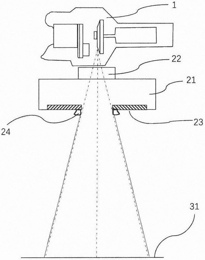
[0031] see figure 1 , figure 2 , the present invention provides a collimator structure for a digital X-ray imaging system, including an X-ray tube connection assembly 22, a collimator housing 21, a collimator blade 23, a collimator blade driving structure (not shown), a radiation field Pointing device 24. The collimator housing 21 is connected to the X-ray tube 1 through the X-ray tube connection assembly 22, and the collimating blades 23 and the driving structure are located in...


PUM


Abstract

A digital X-ray imaging system positioning collimator comprises an X-ray tube connecting assembly, a collimator shell, collimation blades, a collimation blade driving structure and radiation field indicating devices, and the radiation field indicating devices are fixed to the lower edge of each collimation blade on the lowermost layer and synchronously move in an open and close mode along with adjustment of the collimation blades; the radiation field indicating device is provided with a distance sensor which is used for respectively measuring the opening distance of the blades on the two sides of each group of collimation blades; the controller obtains a control angle value through calculation according to data measured by the distance sensor and controls the motor to drive the rotating structure to rotate to a specific angle, so that the light emitting angle of the indicator lamp is adjusted, and reliable visual indication is provided for the X-ray radiation range.

Description

technical field [0001] The application relates to the field of radiation medical devices, in particular to a positioning collimator for a digital X-ray imaging system. Background technique [0002] The digital X-ray imaging system is also called DR. The collimator is an electromechanical optical device installed under the X-ray tube. Its main function is to control the X-ray beam output field of the X-ray tube to meet the needs of X-ray imaging diagnosis and focus the radiation beam. To an anatomical area to reduce unnecessary dose to patients, remove redundant masking areas before diagnostic image processing, avoid affecting image enhancement algorithms, in order to improve image clarity. [0003] The collimator controls the X-ray irradiation field by opening and closing the shielding lead sheet, and the manual collimator realizes the opening and closing action and range of the shielding collimation blades by manually adjusting the knob on the collimator. In order to visua...

Claims


Application Information

Patent Timeline
Patent Type & Authority Applications(China)
IPC IPC(8): A61B6/06
Inventor 毛瑞黄鑫颜青余
Owner SICHUAN ACADEMY OF MEDICAL SCI SICHUAN PROVINCIAL PEOPLES HOSPITAL
Why Eureka
Try Eureka