Needle assembly for a blood sampling device

a blood sampling and needle assembly technology, applied in the direction of infusion needles, sensors, diagnostics, etc., can solve the problems of wasting operative's time, unable to ensure the needle point, and unable to provide reliable visual indication, so as to achieve cost-effective and reliable visual indication

Inactive Publication Date: 2007-04-19
SAFE T OF LAUREL HOUSE
View PDF11 Cites 9 Cited by
  • Summary
  • Abstract
  • Description
  • Claims
  • Application Information

AI Technical Summary

Benefits of technology

[0013] An object of the invention is to overcome all the aforesaid problems and provide a cost-effective needle assembly for a body fluid sampling device which will, without any risk of leakage, provide a reliable visual indication that the needle tip is correctly located in a vein before a pre-evacuated collection tube is applied.
[0016] As needles conventionally used in blood sampling devices may have an outer diameter (OD) of about 0.9 to 1.0 mm, the passageway between the needle ends may be as little as 0.8 mm wide in many embodiments of the present invention. Only the end sections of the passageway where end regions of the needles are accommodated need to be equal to the OD of the needles. Thus, in accordance with the invention there is no intermediate chamber to which blood must pass in order to be observed and no requirement for venting such chamber. Indeed, there is no possibility of leakage because of the one piece hub formation.
[0019] Conventional multi-sample needles have an elastomeric sheath over the distal end of the needle to prevent the uncontrolled escape of blood between the application of a number of pre-evacuated (or piston evacuated) sample tubes. This sheath is pierced by the point of the distal end of the needle when the sample tube is applied and is pushed back down the needle by the septum of the sample tube. When the sample tube is removed, the sheath moves back over the needle point (due to its elasticity) and seals it, thus preventing the uncontrolled escape of blood under the natural blood pressure within the body of the patient.
[0022] Advantageously at least part of the visible passageway between the proximal ends of the needles is magnified so that a user may more easily witness introduction of blood or other body fluid into said passageway. Thus, a magnifying formation acting as a magnifying lens preferably overlies at least part of the passageway.
[0023] Because this invention requires two separate needles, it permits another advantageous development, namely the displacement of one of the two needles out of alignment with the axis of the other of the two needles.
[0025] Such an offset disposition for the patient piercing needle has the advantage of allowing a lower angle of entry into the patient. This makes it easier to locate the needle tip into a vein without piercing the other (inner) wall of the vein, which is often a difficult task, particularly in very young, elderly or overweight patients.

Problems solved by technology

If this air is simply vented to the atmosphere or evacuated by vacuum or other suction method, as in the prior art, there is no way that the operative can be sure that the needle point is in fact in a true vein and not in a minor blood vessel.
This potential error can lead to the waste of the operative's time, much discomfort to the patient and a financial loss due the waste of only partially filled sample tubes which must be discarded.

Method used


Image

  • Needle assembly for a blood sampling device
  • Needle assembly for a blood sampling device
  • Needle assembly for a blood sampling device

Examples


Embodiment Construction

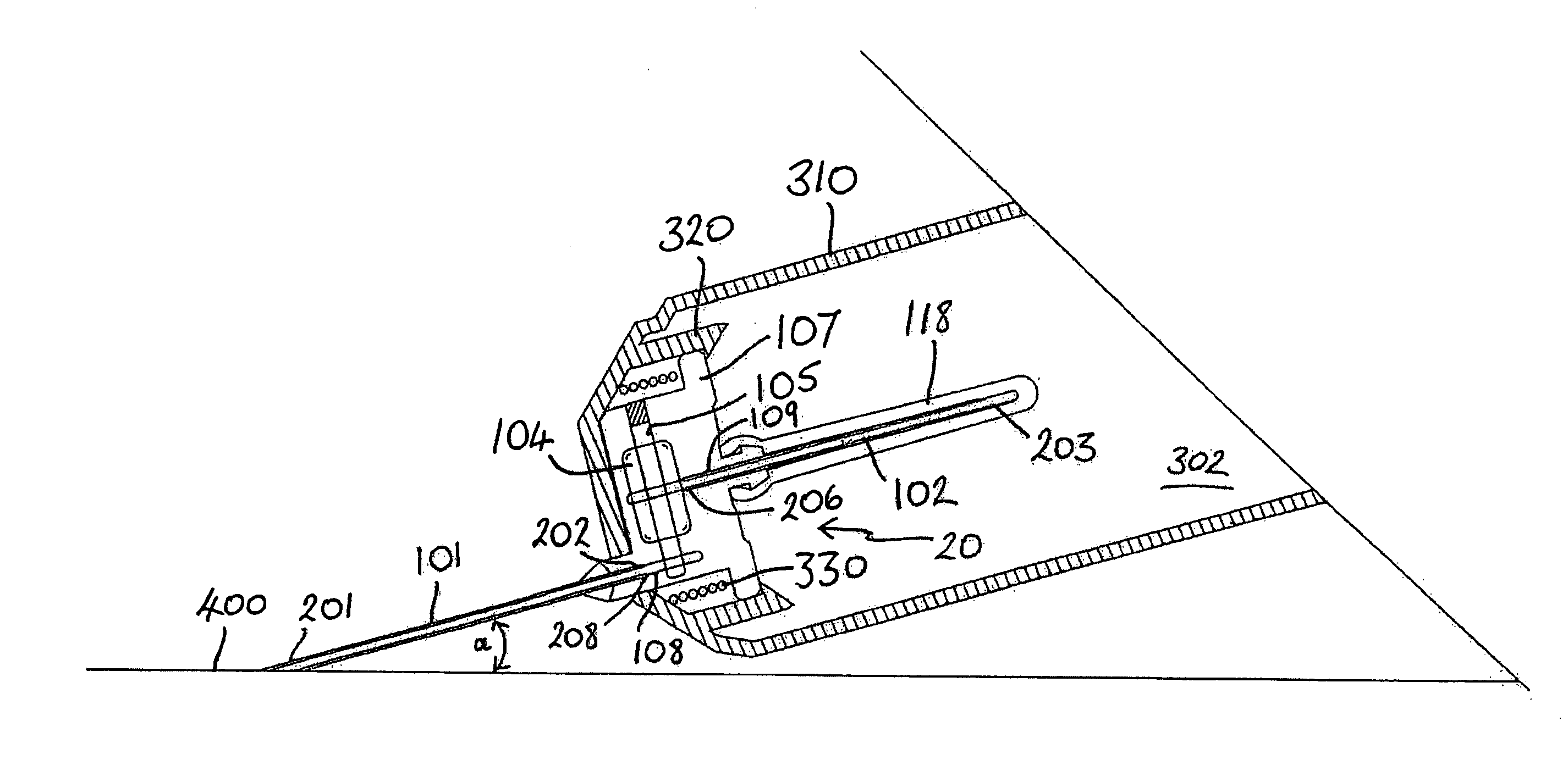
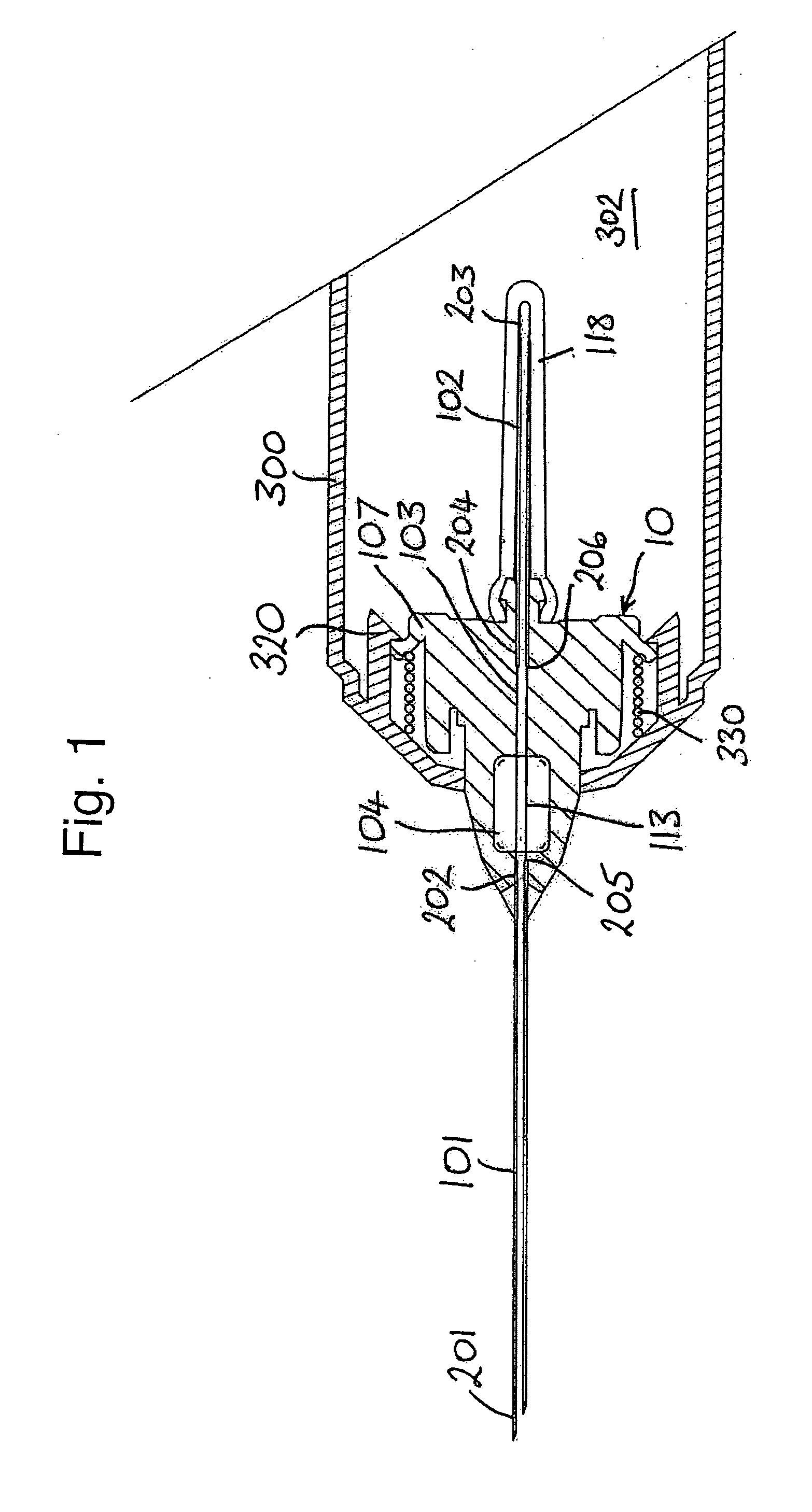
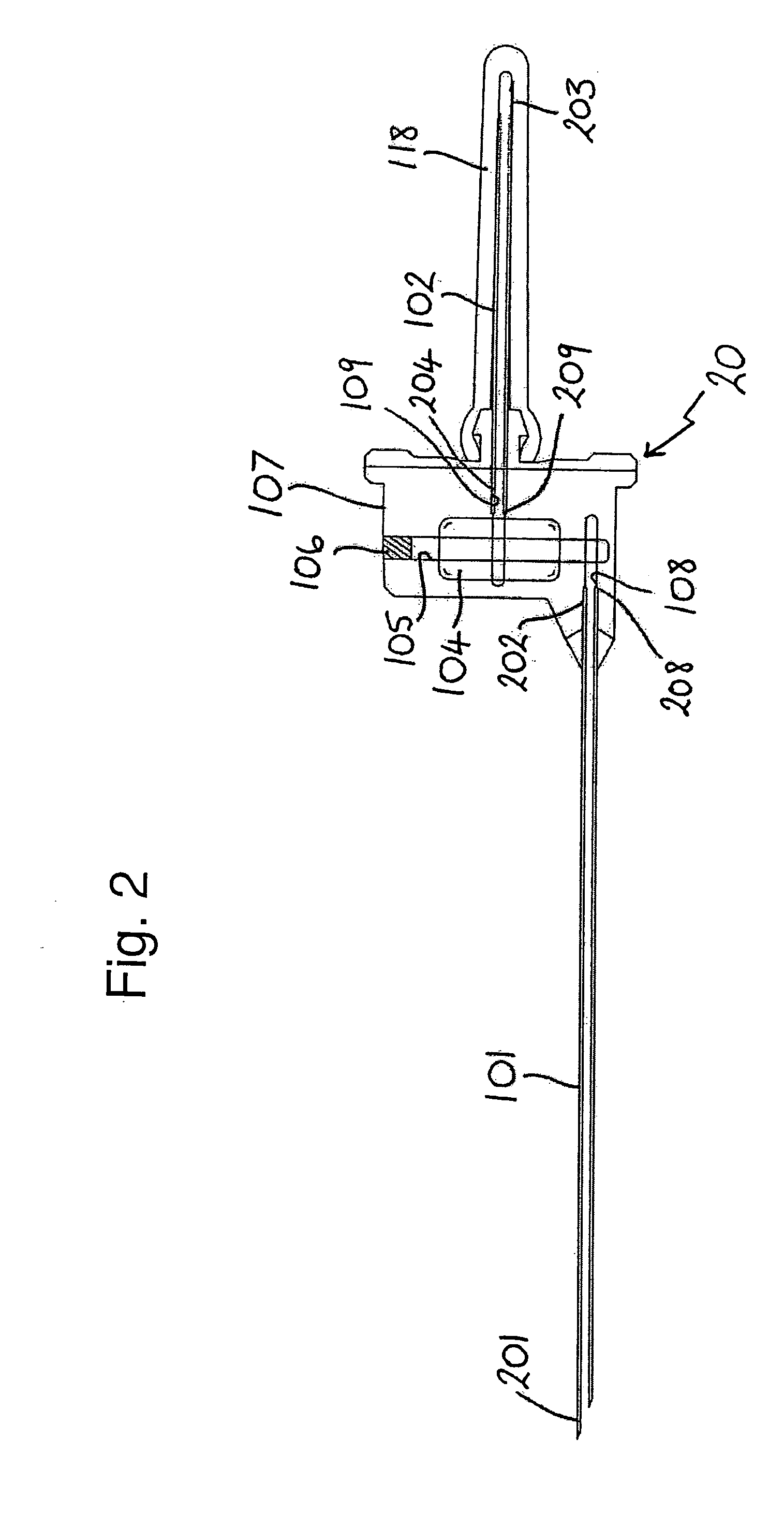
[0036] Referring to FIG. 1, a first embodiment of the invention is an in-line witnessing multi-sample needle assembly 10. It comprises a first hollow hypodermic needle 101, a second hollow hypodermic needle 102, a hub 107 and a flexible elastomeric sheath 118 over the second needle 102. The first and second needles 101, 102 extend from opposed ends of the hub 107 in alignment with each other, i.e. co-incident axes.

[0037] Both of the needles 101, 102 are necessarily of stainless steel or comparable material to meet required standards for medical devices.

[0038] The first needle 101 has, at one end, a multi-ground point 201 for penetration of a patients' skin and vein wall, while its other end 202 is plain and is bonded to the hub 107. The second needle 102 also has a ground point 203 at its free end, which is for piercing of a septum of a pre-evacuated blood sampling tube (not shown). The elastomeric sheath 118 would also be pierced in that operation. The other end 204 of the second...


PUM


Abstract

First and second hollow needles extend from opposing sides of a common hub which is formed in one piece of transparent material. Proximal ends of the respective needles are in communication with each other by a narrow passageway through the hub. The projecting portion of the second needle is covered by an elastomeric sheath. The hub preferably includes a magnifying formation overlying the passageway portion between the proximal ends of the needles. In use, once the point of the first needle penetrates a vein, the patient's blood pressure is sufficient to displace air from the entire first needle and at least part of the passageway through the hub. The sheath over the second needle is sufficiently elastic to allow this and expand accordingly. The blood flows into the piercing needle and the passageway between the needles, thus being viewable through the surrounding transparent material and the magnifying portion, if present.

Description

[0001] This is a continuation-in-part of International Application PCT / GB2005 / 001061, with an international filing date of Mar. 22, 2005. Priority is claimed to United Kingdom Application Serial No. GB 0406438.2, filed on Mar. 23, 2004, which is hereby incorporated by reference.TECHNICAL FIELD OF THE INVENTION [0002] This invention concerns a needle assembly for a blood sampling device. BACKGROUND ART [0003] Conventional blood samplers comprise a hollow needle mounted in and extending through a hub, by means of which the device may be held by a user and optionally mounted within a holder or the like. The needle is of stainless steel and has a sharp point at each end. One end is intended for insertion into a patient's vein. The other end is designed for insertion into a pre-evacuated collection tube, its sharp point being necessary to pierce a sealed septum of the collection tube. With the first end appropriately inserted into a vein, blood is sucked into the collection tube by vacuu...

Claims


Application Information

Patent Timeline
Patent Type & Authority Applications(United States)
IPC IPC(8): A61B5/00A61M5/32A61B5/15A61B10/00A61M5/34A61M25/06
CPCA61B5/1411A61M5/3234A61M2005/3236A61M2005/341A61B5/15003A61B5/150297A61B5/150389A61B5/150496A61B5/150526A61B5/150572A61B5/150633A61B5/150732A61B5/1545
Inventor JEFFREY, PETER
Owner SAFE T OF LAUREL HOUSE
Why Eureka
Try Eureka