[0029] Example one
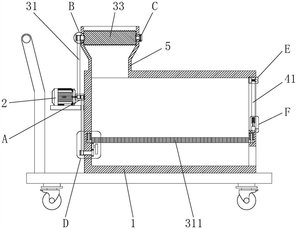
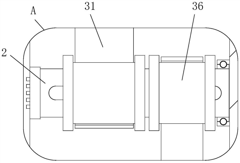
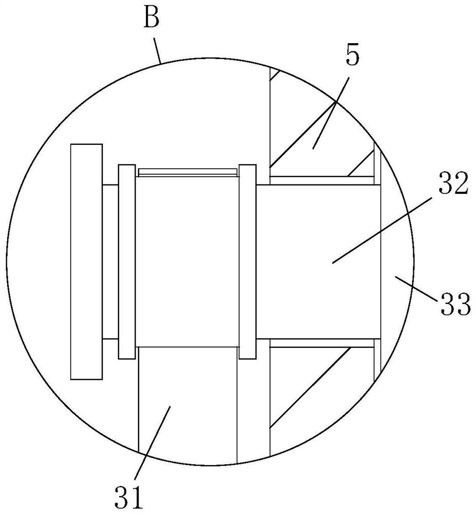
[0030] See Figure 1-9 As shown, a boiler biomass transport device, including the device main body 1, the motor 2, and the feed port 5; one side of the apparatus main body 1 is provided with a motor 2, and the feed port 5 is opened on one side of the tip end of the apparatus main body 1. The device main body 1 is provided with a pulverized screening mechanism; the pulverized screening mechanism includes a first transmission belt 31, a connecting shaft 32, a broken roller 33, an active gear 34, a driven gear 35, a second drive belt 36, The transmission shaft 37, the rotating gear 38, the passive gear 39, and the screening assembly are arranged on the output shaft of the motor 2, and the other end of the first transmission belt 31 is disposed at the connecting shaft 32. On the outside, the connecting shaft 32 penetrates through the crushing roller 33, and the crushing roller 33 is provided with two sets, the active gear 34 and the connecting shaft 32 fixedly connected to one end of the first transmission belt 31, the driven gear 35 and active The gear 34 is engaged, and the driven gear 35 is fixed to the other set of crushing rollers 33, and one end of the second drive belt 36 is disposed at the output shaft, and the other end of the second transmission belt 36 is provided in the drive shaft 37. On the outside, the transmission shaft 37 and the apparatus main body 1 are connected by a bearing active, the rotating gear 38 fixedly coupled to the drive shaft 37 away from the second drive belt 36, the passive gear 39 meshes and passive The gear 39 is attached to the inner wall of the apparatus main body 1 via a bearing activity, the screening assembly disposed at a position where the device main body 1 is close to the bottom end.
[0031]When working, the device is rotated by the first transmission belt 31 and the connecting shaft 32 by the first transmission belt 31 and the connecting shaft 32, and the connection shaft 32 is rotated while the connection shaft 32 is fixed. The active gear 34 of the first transmission belt 31 is also rotated, and the engaged driven gear 35 is rotated, so that the driven gear 35 is fixed to the other set of crushing roller 33 is also synchronized, two sets of crushing rolls 33 Turn in the opposite direction to be involved in the biomass fuel input from the top end of the feed port 5 between the two sets of crushing rollers 33, the biomass fuel, which is pulverized, and the smaller sandstone and the like fall into the screen. Above 311.
[0032] The screening assembly includes a cam 310, a screen 311, a slider 312, a rail 313, a slide 314, and a reset spring 315, and the cam 310 is fixedly coupled to the passive gear 39, the screen 311 is disposed in the cam 310 The slider 312 is fixed to both sides of the screen 311, and the slider 312 is sleeved outside the slide rail 313, the slide rail 313 fixedly coupled to the inside of the chute 314, the chute 314 opens On both sides of the inner wall of the device body 1 close to the bottom end position, the reset spring 315 is wound outside the rail 313,
[0033] When the motor 2 is rotated when the motor 2 is rotated by the first transmission belt 31, the transmission shaft 37 is rotated by the second drive belt 36, and the transmission shaft 37 rotates the rotation gear 38 that drives the fixed connection to rotate and rotates the gear. 38 Turn the driven gear 39 to rotate, so that the passive gear 39 is fixed to the cam 310 to rotate, the cam 310 is designed, the cam 310 periodically 311 Tap, move the screen 311, moves upward and drives the slider 312 to slide in the inside of the chute 314, so that the chute 314 generates extrusion to the reset spring 315 The elasticity changes, when the cam 310 disappears with the impact force of the screen 311, the slider 312 is restored to the original position under the reduction force of the reset spring 315, and the process is recycled when the motor 2 is working in operation, thereby playing The role of the biomass fuel over the screen 311 is sieved to make the fine sandstone of the biomass fuel inside the screen 311;
[0034] The reset spring 315 is fixed to one end of the slider 312 and the slider 312 is fixed, and the reset spring 315 is fixed from one end of the slider 312 fixed to the inside of the chute 314,
[0035] When working, the effect of automatically resetting the slider 312 is carried out by the reset spring 315;
[0036] The apparatus main body 1 is provided with a blocking mechanism from one side of the motor 2, the blocking mechanism including the main barrier plate 41, a stopper 42, a fixing assembly, and a composite component, and the main barrier 41 is disposed in the device main body 1 away from the motor. One end of 2, the stopper 42 is fixed to the apparatus main body 1, the fixing assembly is disposed at the top end of the main block 41, the engaging component being disposed at the bottom end of the main block 41,
[0037] When the biomass fuel is to be taken during operation, the rotation of the knob 46 is first driven to cause the block 45 and the threaded post 44 to cause the thread 44 to drive the block 45 to move away from the main stopper 41. , The block 45 is released in a state in which the main barrier 41 is tightly bonded, and when the thread 44 is completely disengaged from the inside of the connecting post 43, the limit effect is released to the main block 41; at this time, the handle 413 Move up, the handle 413 drives the bottom baffle 410 to move upward, so that the socket 411 releases the engagement with the slot 412, the connecting block 49 enters the interior of the engagement chamber 47 and generates extrusion of the engagement spring 48 The engaging spring 48 generates an elasticity that pulled the handle 413 toward the side of the apparatus main body 1 toward the side of the apparatus main body 1 when the plug 411 released the engagement with the slot 412. Connect, the main barrier 41 is removed, and the biomass inside the device main body 1 can be taken;
[0038] The fixing assembly includes a connection post 43, a thread 44, and a block 45, and the connecting post 43 is fixedly coupled to the stopper 42, the threaded column 44 threads being coupled to the inside of the connecting post 43, the disguised block 45 fixed connection The threaded column 44 is away from the side of the connection post 43, and the block 45 is closely fitted with the main barrier 41,
[0039] When the biomass fuel is to be taken during operation, the rotation of the knob 46 is first driven to cause the block 45 and the threaded post 44 to cause the thread 44 to drive the block 45 to move away from the main stopper 41. The block 45 is released in a state in which the main barrier 41 is tightly bonded, and when the thread 44 is completely disengaged from the inside of the connecting post 43, the limit effect of the main stopper 41 is released;
[0040] The abutment block 45 is fixed from one side of the connection post 43 to be connected to the knob 46, and the outer side of the knob 46 is opened,
[0041] When working, the effect of rotating the connecting post 43 and the block 45 by the knob 46, the effect of the anti-skating of the knob 46 is increased to increase the friction, preventing pulling the knob 46 while rotating.
[0042] The engaging assembly includes a engaging chamber 47, a engaging spring 48, a connection block 49, a bottom blade 410, a block 411, a slot 412, and a handle 413, and a handle 47, which is opened in the main barrier 41. The bottom end, the engaging spring 48 is disposed inside the engaging chamber 47, the connection block 49 is disposed in the interior of the engaging chamber 47 near the engagement spring 48, the bottom baffle 410 and the connecting block 49 is moving away from one end of the engaging spring 48, the slug 411 is fixed to one end of the connecting block 49 away from the connection block 49, and the socket 411 is inserted inside the slot 412, the slot 412 is open. On the side of the apparatus main body 1, the handle 413 is fixed to the side of the bottom plate 410,
[0043] When working, the handle 413 is pulled upward, and the handle 413 is moved upwards to move the bottom baffle 410, so that the socket 411 releases the engagement with the slot 412, and the connection block 49 enters the interior of the engagement cavity 47 and the card The spring 48 generates a squeezing to generate an elastic shape that causes the engagement spring 48 to release the handle 413 toward the side of the device main body 1 to the side of the device main body 1 at this time when the interposer 411 is released. The connection between the device main body 1, the main barrier 41 is removed, and the biomass inside the device body 1 can be taken.
[0044] The two sides of the inside of the inside of the card compartment 47 are fixedly connected to the movable block 414, and the movable block 414 is slid to be connected inside the movable tank 415, the movable tank 415 being opened on both sides of the connecting block 49,
[0045] When the connecting block 49 is moved during operation, the movable block 414 is sliding in the inside of the movable groove 415, and the active block 414 and the movable groove 415 are combined to reduce the connection block 49 in progress and the engagement cavity. The effect of the friction between the inner walls, preventing the connection block 49 from moving with the friction between the inner wall of the engagement chamber 47, so that the connecting block 49 is more smooth, while passing the movable block 414 The action combined with the movable tank 415 acts as a limit on the moving distance of the connecting block 49, preventing the effect of the connection block 49 from being detached from the interior of the engaging chamber 47.
[0046] The working principle, the device is rotated by the first transmission belt 31 and the connecting shaft 32 when performing operation, and the connection shaft 32 is rotated while the connection shaft 32 is rotated while fixing the connection shaft 32 away. The active gear 34 of the first transmission belt 31 is also rotated, and the engaged driven gear 35 is rotated, so that the driven gear 35 is fixed to the other set of crushing roller 33 is also synchronized, two sets of crushing rolls 33 Turn in the opposite direction to be involved in the biomass fuel input from the top end of the feed port 5 between the two sets of crushing rollers 33, the biomass fuel, which is pulverized, and the smaller sandstone and the like fall into the screen. Above 311.
[0047] When the motor 2 is rotated by the first transmission belt 31, the transmission shaft 37 is rotated by the second drive belt 36, and the transmission shaft 37 rotates the rotation gear 38 that drives the fixed connection to rotate, and the rotation gear 38 rotates to drive The engaged passive gear 39 is rotated, so that the passive gear 39 is fixed to the cam 310 to rotate in the cam 310 as a circular shape, due to the special shape design of the cam 310, the cam 310 is periodically knocked on the screen 311 Hit, when the screen 311 is moved upward when the screen 311 is hit and drives the slider 312 to slide in the inside of the chute 314, so that the slot 314 generates extrusion to the reset spring 315, so that the reset spring 315 generates elasticity. When the cam 310 disappears with the impact force of the screen 311, the slider 312 is restored to the original position under the reduction force of the reset spring 315, and when the motor 2 is reciprocated, it is served in the screen 311. The role of the above biomass fuel is sieved to make the fine sandstone of the biomass fuel inside through the aperture on the screen 311.
[0048] When the biomass fuel within the device body 1 is to be taken, the rotation of the knob 46 is first driven against the block 45 and the threaded column 44 to generate rotation, so that the threaded column 44 drives the block 45 to move away from the main stopper 41, so that The block 45 releases the state in which the main stop 41 is tightly bonded, and when the thread 44 is completely disengaged from the inside of the connection post 43, the block 45 is released to the main stopper 41; at this time, the handle 413 is pulled upward. The handle 413 drives the bottom baffle 410 to move upwards, so that the socket 411 releases the engagement with the slot 412, the connecting block 49 enters the interior of the engaging chamber 47 and generates an extrusion of the engagement spring 48 to engage the spring spring. 48 Generate an elasticity change, when the block 411 is released to pull the handle 413 toward the side of the shuttle away from the device main body 1 at this time, the main baffle 41 completely releases the connection between the main body 1, the main The baffle 41 is removed, and the biomass inside the device main body 1 can be taken.
[0049] When the connecting block 49 is moved during movement, the movable block 414 is slidably in the inside of the movable groove 415, and the active block 414 and the active groove 415 are combined to reduce the connecting block 49 in the inner wall of the interior The effect of friction, preventing the connection block 49 from being moved between the interior walls of the engagement chamber 49, and causes the connection block 49 more smooth when moving, and simultaneously passed the movable block 414 and the movable tank. The action of the combination of 415 acts as a limit to the moving distance of the connection block 49, preventing the effect of the connection block 49 from being detached from the interior of the engaging chamber 47.