Centrifugal tube

A technology of centrifuge tubes and connectors, which is applied in the field of medical devices, can solve the problems of cumbersome operation and large-scale use of centrifuge tubes, and achieve the effects of saving equipment costs, improving extraction efficiency and safety, and reducing steps and time

Pending Publication Date: 2019-01-15
PLASTIC SURGERY HOSPITAL CHINESE ACAD OF MEDICAL SCI
View PDF0 Cites 1 Cited by
  • Summary
  • Abstract
  • Description
  • Claims
  • Application Information

AI Technical Summary

Problems solved by technology

During the process, the centrifuge tubes need to be replaced many times, which not only causes a large number of centrifuge tubes to be u

Method used


Image

  • Centrifugal tube
  • Centrifugal tube
  • Centrifugal tube

Examples


Embodiment 1

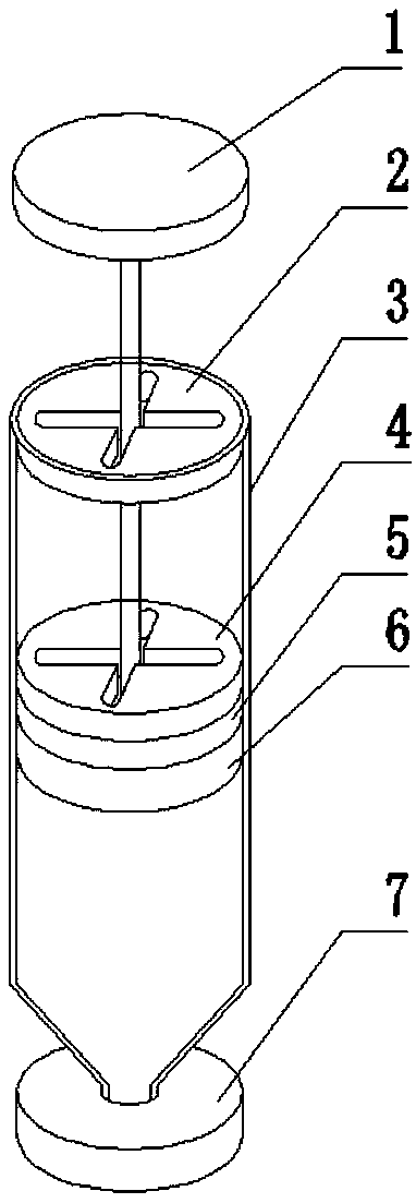
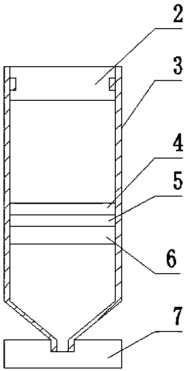
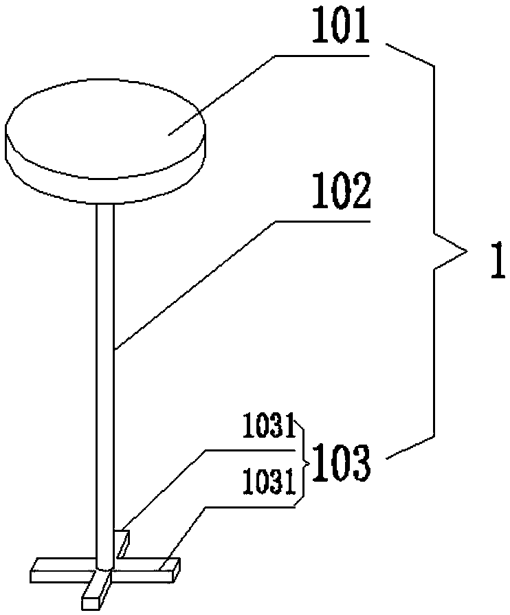
[0045] Such as figure 1 and figure 2 As shown, a centrifuge tube includes a centrifuge tube body 3, a handle 1, a connector, a seal 6 and a bottom cover 7, the bottom of the centrifuge tube body 3 has a bottom opening, and the bottom cover 7 is connected to the bottom opening connected, the connecting piece is fixedly connected with the sealing piece 6 and arranged in the centrifuge tube body 3, the sealing piece 6 is in sealing connection with the inner wall of the centrifuge tube body 3, and the handle 1 is inserted into the centrifuge tube body 3 The centrifuge tube body 3 is connected with the connector.

[0046] Specifically, the centrifuge tube body 3 is a hollow tube body, the side wall of the centrifuge tube body 3 is cylindrical, and the bottom is funnel-shaped.

[0047] Specifically, the connecting part is glued to the sealing part 6 .

[0048] Specifically, the sealing member 6 is made of rubber.

[0049] Preferably, the centrifuge tube body 3 is made of medica...

Embodiment 2

[0073] On the basis of Example 1, such as Figure 6 As shown, the connecting piece can also be a locking plate 9, the locking plate 9 has a locking through hole adapted to the push head 103, the locking plate 9 is fixedly connected with the sealing member 6, the The side of the locking plate 9 connected to the sealing member 6 has a fan-shaped locking groove opening downward.

[0074] Figure 6 The locking plate 9 shown in is a view of the side of the locking plate 9 facing the sealing member 6 , and the locking plate 9 is bonded to the sealing member 6 . The locking plate 9 has a cross hole, and the push head 103 of the handle 1 passes through the handle hole of the top cover 2 , passes through the cross hole of the locking plate 9 until it contacts the sealing member 6 . At this time, the pusher 101 is positioned at the outside of the centrifuge tube body 3, and the rotating pusher 101 drives the pusher 103 to rotate in the fan-shaped locking groove of the locking plate 9 ...


PUM

PropertyMeasurementUnit
Diameteraaaaaaaaaa

Abstract

A centrifuge tube includes a centrifugal tube body, a handle, a connecting member, a seal member and a bottom cover. The bottom of the centrifugal tube body is provided with a bottom port, the bottomcover is connected with the bottom port, the connecting member is fixedly connected with the seal member and arranged in the centrifugal tube body, the seal member is sealingly connected with the inner wall of the centrifugal tube body, and the handle is inserted into the centrifugal tube body and detachably connected with the connecting member. The centrifugal tube of the invention can realize layered liquid extraction and adding reagent, improve extraction efficiency and safety, and save instrument cost.

Description

technical field [0001] The invention relates to the field of medical instruments, in particular to a centrifuge tube. Background technique [0002] In the field of biological sciences, centrifugal technology has been widely used. Centrifugation technology is one of the most commonly used methods for the separation of proteins, enzymes, nucleic acids and cell subcomponents, and it is also a commonly used separation, purification or clarification method in biochemical laboratories. The sample suspension is placed in a centrifuge tube under high-speed rotation. Due to the huge centrifugal force, the suspended tiny particles (such as cell organelles, precipitation of biological macromolecules, etc.) settle at a certain speed, thereby being separated from the solution. [0003] The centrifuge tubes currently used are all traditional tube caps and tube body structures. The solution that needs to be centrifuged is added to the centrifuge tube through a pipette gun, and the centrif...

Claims


Application Information

Patent Timeline
IPC IPC(8): C12M1/24
CPCC12M1/24
Inventor 李梓菲栾杰王黔穆大力刘春军辛敏强付苏
Owner PLASTIC SURGERY HOSPITAL CHINESE ACAD OF MEDICAL SCI
Why Eureka
Try Eureka