
Automatic film pasting and conveying system for display frame

A conveying system and film sticking technology, applied in the directions of transportation and packaging, packaging machines, packaging, etc., can solve the problems of increasing labor intensity, affecting the film sticking work of film components, and the positioning of fixture components.

Active Publication Date: 2022-04-12
常州市桑豪车辆配件有限公司 +1
View PDF11 Cites 0 Cited by
  • Summary
  • Abstract
  • Description
  • Claims
  • Application Information

AI Technical Summary

Problems solved by technology

[0003] After the clamp assembly is placed on the conveyor belt, the conveyor belt drives the clamp assembly to move towards the film assembly, thereby completing the effect of automatic film application, but the clamp assembly does not position the clamp assembly after it is placed on the upper end of the conveyor belt, so when the clamp assembly moves to When the film assembly is under the position, the fixture assembly will not move to the designated position, which will affect the film application work of the film assembly; at the same time, the powdery and granular ferromagnetic impurities adsorbed by the static elimination rod will always be adsorbed on the static elimination rod. Regular manual cleaning increases the labor intensity, and long-term accumulation will affect the static elimination effect of the static elimination bar

Method used


Image

  • Automatic film pasting and conveying system for display frame
  • Automatic film pasting and conveying system for display frame
  • Automatic film pasting and conveying system for display frame

Examples


Embodiment Construction

[0059] The present invention is described in further detail now in conjunction with accompanying drawing. These drawings are all simplified schematic diagrams, which only illustrate the basic structure of the present invention in a schematic manner, so they only show the configurations related to the present invention.

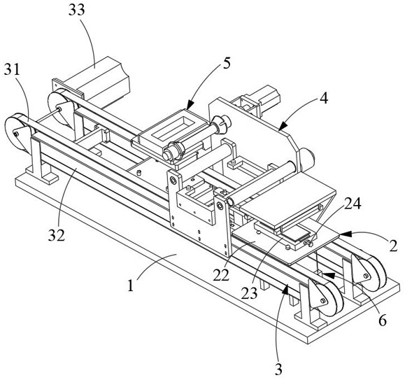
[0060] Such as figure 1 As shown, a display frame automatic film-attaching conveying system of the present invention includes: a workbench 1, a work clamp assembly 2, a conveying part 3, a film-applying part 4, a pressing part 5 and several positioning parts 6, and the conveying part 3 is set On the workbench 1, the conveying part 3 is suitable for conveying the clamp assembly 2; the conveying part 3 includes a conveyor belt 31, a conveying bracket 32 ​​and a conveying motor 33, and the conveying bracket 32 ​​is fixed on the workbench 1, the conveyor belt 31 surrounds the conveyor bracket 32, the conveyor motor 33 is fixed on one side of the conveyor bracket ...


PUM


Abstract

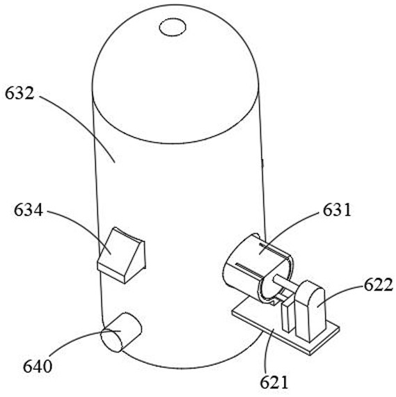
The invention relates to the technical field of display screen automation, in particular to an automatic film pasting and conveying system for a display frame. The invention relates to an automatic display frame film pasting and conveying system which is characterized in that a plurality of limiting holes are symmetrically formed in a workpiece clamping assembly, and the workpiece clamping assembly is suitable for clamping and fixing a workpiece; the positioning parts are fixed to the workbench in a liftable mode, each positioning part comprises a lifting air cylinder, a rotating assembly and a positioning assembly, the lifting air cylinders are vertically fixed to the workbench, the rotating assemblies are horizontally fixed to the movable ends of the lifting air cylinders, and the positioning assemblies are rotatably fixed to the rotating ends of the rotating assemblies; the rotating assembly drives the positioning assembly to rotate in an arc mode so that the positioning assembly can be inserted into the corresponding limiting hole. The lower end face of the clamping assembly abuts against the outer wall of the positioning assembly so that the positioning assembly can be separated from the rotating assembly. And after the positioning assembly stops rotating and keeps vertical, the lifting air cylinder drives the positioning assembly to move downwards, so that the positioning assembly is separated from the workpiece clamping assembly.

Description

technical field [0001] The invention relates to the technical field of display screen automation, in particular to an automatic film-sticking conveying system for a display frame. Background technique [0002] Application number: CN202010898538.4, publication (announcement) number: CN112224508A, an automatic film sticking device for LCD display. The invention discloses an automatic film sticking device for LCD display. The conveyor belt is equipped with a clamp assembly, the clamp assembly includes a clamp base plate, a splint is provided on the clamp base plate, an LCD display is provided inside the clamp plate, and a film assembly is provided on one side of the conveying assembly, and the film assembly includes a film receiving shaft and a film output shaft , the conveyor belt is provided with an array of lamination rotating shafts, an array of first air cylinders is arranged under the lamination shaft, and a pressing assembly is provided on one side of the film sticking a...

Claims


Application Information

Patent Timeline
IPC IPC(8): B65B33/02B65B35/24B65B65/00
Inventor 周传生孟亮刘华彬徐武彬余梦嫒李远
Owner 常州市桑豪车辆配件有限公司
Learn More