Continuous intelligent pulp discharging and crushing production line and pulp discharging and crushing method

A production line and unloading technology, applied in the direction of raw material separation, etc., can solve the problems of complex installation, falling, complex structure design, etc., and achieve the effect of reducing physical labor, reducing errors, and simple structure

Active Publication Date: 2022-04-12
SHANDONG TIANYANG PAPER
View PDF5 Cites 0 Cited by
  • Summary
  • Abstract
  • Description
  • Claims
  • Application Information

AI Technical Summary

Problems solved by technology

[0003] First, at present, many production lines still use manual feeding in the pulp board feeding process.
[0004] Feeding needs to stand beside the pulper and push the pulp board directly by hand. On the one hand, personnel are prone to slip, fall, or even fall into the pulper, causing accidents; on the other hand, the quality of the pulp is not good. Feeding, pulp boards are not evenly put in, and sometimes a whole bag will be pushed in, which will easily cause uneven pulp concentration, affect the beating degree of pulp, and thus affect product quality
[0005] Although some automatic feeding devices are also disclosed in some patents, due to their complicated structural design, high cost and complicated installation, the practical value is too low to be promoted, and most of the devices push the pulp board into the whole package. To the crushing tank, affecting the quality of slurry
[0006] Second, at present, the weight of the pulp board and the amount of clean water added need to be calculated manually, and the clean water valve must be manually opened and closed

Method used


Image

  • Continuous intelligent pulp discharging and crushing production line and pulp discharging and crushing method
  • Continuous intelligent pulp discharging and crushing production line and pulp discharging and crushing method

Examples


Embodiment Construction

[0025] It should be noted that the following detailed description is exemplary and intended to provide further explanation of the present invention. Unless defined otherwise, all technical and scientific terms used herein have the same meaning as commonly understood by one of ordinary skill in the art to which this invention belongs.

[0026] It should be noted that the terminology used here is only for describing specific embodiments, and is not intended to limit exemplary embodiments according to the present invention. As used herein, unless the invention clearly states otherwise, the singular form is also intended to include the plural form. In addition, it should also be understood that when the terms "comprising" and / or "comprising" are used in this specification, their Indicate the presence of features, steps, operations, means, components and / or combinations thereof;

[0027] For the convenience of description, if the words "up", "down", "left" and "right" appear in th...


PUM


Abstract

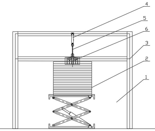
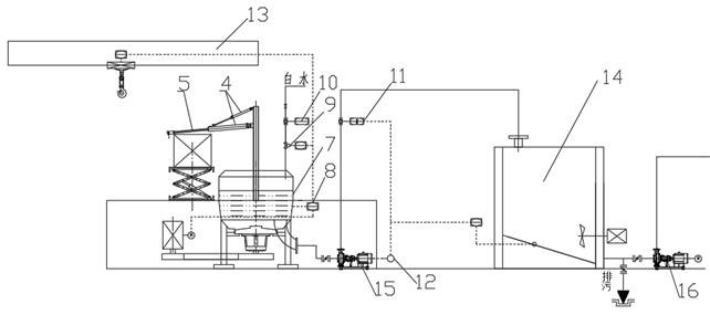
The invention discloses a continuous intelligent pulp discharging and crushing production line and a pulp discharging and crushing method in order to solve the problems of low pulp quality and the like in the pulp discharging and crushing process, and the production line comprises a hoisting device, an automatic discharging device, a pulper and a control system; the automatic discharging device comprises a vertical lifting device, a support, an air cylinder, a telescopic pull arm and a pull plate, the lifting device lifts a pulp board to the vertical lifting device, the vertical lifting device is arranged on one side of the pulper, the pulper is arranged below the support, the air cylinder is located above the pull arm, one end of the air cylinder is hinged to the support, and the other end of the air cylinder is hinged to the telescopic pull arm. One end of the telescopic pull arm is hinged to the support, the other end of the telescopic pull arm is provided with a pull plate, and the pull plate pulps the pulp boards into the pulper layer by layer under the control of the telescopic pull arm; the pulper is connected with a water inlet pipe, and a pulp board weighing sensor is arranged on the vertical lifting device; the control system controls the water inlet amount of the water inlet pipe and also controls the air cylinder, the telescopic pull arm and the hoisting device.

Description

technical field [0001] The invention belongs to the field of pulp plate crushing, and in particular relates to a continuous intelligent pulp unloading and crushing production line and a pulp unloading and crushing method. Background technique [0002] The inventor finds that in the current pulp board crushing process, the degree of automation is low, and the reasons for the low degree of automation mainly contain the following aspects: [0003] First, at present, many production lines still use manual feeding in the pulp board feeding process. [0004] Feeding needs to stand beside the pulper and push the pulp board directly by hand. On the one hand, personnel are prone to slip, fall, or even fall into the pulper, causing accidents; on the other hand, the quality of the pulp is not good. When feeding, the pulp board is not evenly put in, and sometimes a whole bag will be pushed in, which will easily cause uneven pulp concentration, affect the beating degree of the pulp, and...

Claims


Application Information

Patent Timeline
IPC IPC(8): D21B1/34
Inventor 刘洪奎王立同王笛刘怀东赵广锡刘兆娟孙佑顺
Owner SHANDONG TIANYANG PAPER
Why Eureka
Try Eureka