Inland river immersed tube floating transportation and installation operation method
An immersed pipe and inland river technology, applied to the field of floating installation of inland river immersed pipes, can solve the problems of inconvenient scheduling, large force on beams, poor stability, etc., and achieve the effects of improving operation efficiency, reducing construction costs and improving stability.
- Summary
- Abstract
- Description
- Claims
- Application Information
AI Technical Summary
Problems solved by technology
Method used
Image

Examples
Embodiment 1
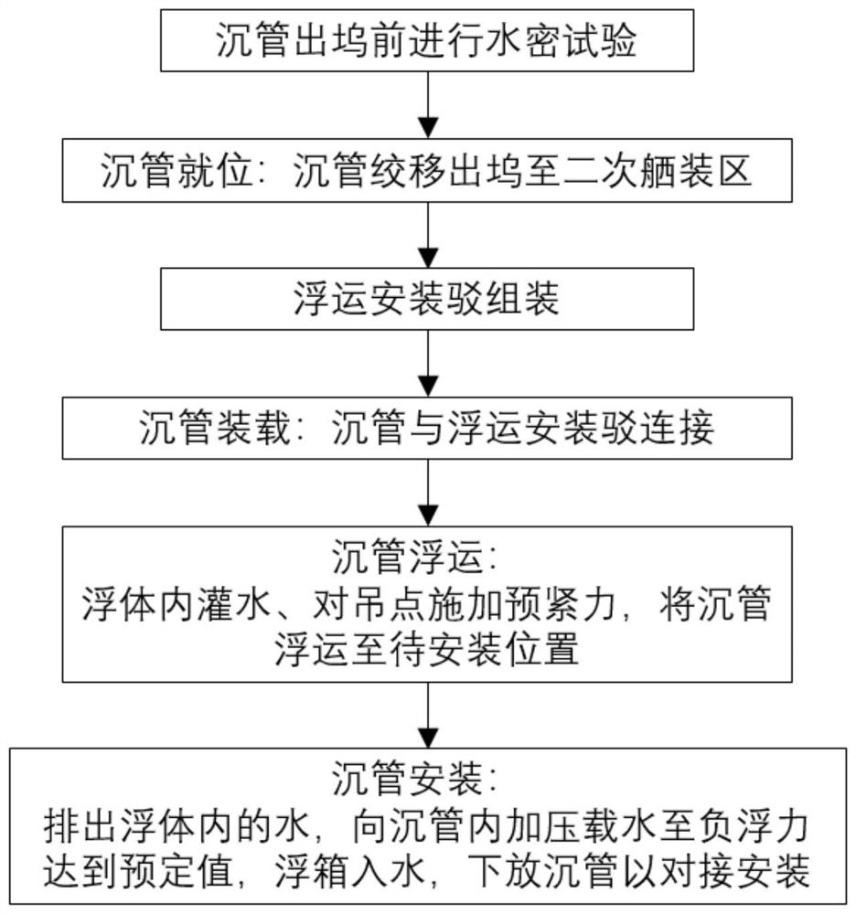
[0036] like figure 1 As shown, the inland river immersed tube floating installation operation method of the present invention includes the steps of placing the immersed tube in place, assembling the floating installation barge, loading the immersed tube, floating the immersed tube, and installing the immersed tube.
[0037] In the step of putting the immersed tube in place, the 5 strands of the immersed tube to be installed by floating are removed from the dock and moved to the secondary outfitting area for secondary outfitting.
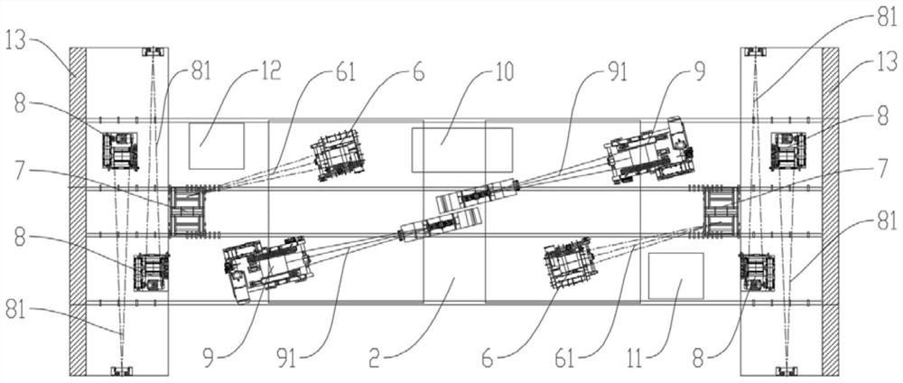
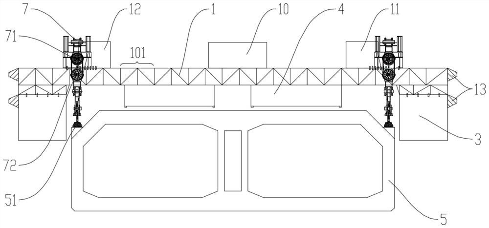
[0038] In the step of assembling the floating installation barge, the assembly of two sub-floating installation barges is included. like figure 2 , image 3As shown, the assembly of each sub-floating installation barge further includes: connecting a plurality of sub-trusses 101 to the main truss 1 in sequence, connecting two floating bodies 3 to the bottom surfaces of both ends of the main truss 1 in the length direction, and connecting at least o...
Embodiment 2
[0053] Such as Figure 8 , Figure 9 As shown, the present invention also provides a method for floating installation of immersed pipes in inland rivers. On the basis of Embodiment 1, two ends of the two main trusses 1 in the length direction of the two sub-floating installation barges are respectively connected to each other. The connecting trusses 14 connect the reinforcing trusses 15 between the two connecting trusses 14 , and the connecting trusses 14 and the reinforcing trusses 15 are formed by detachable connection of a plurality of sub-trusses 101 .
[0054] It can be understood that the length of the connecting truss 15 can be adjusted according to the length of the immersed tube 5 by increasing or decreasing the number of sub-trusses 101; The position of the lifting point 51, and the length of the connecting truss 14 depends on the distance between the two main trusses 1 of the two sub-floating installation barges. In addition, the length of the reinforcing truss 15...
PUM
 Abstract
Description
Claims
Application Information
 - Generate Ideas
- Intellectual Property
- Life Sciences
- Materials
- Tech Scout
- Unparalleled Data Quality
- Higher Quality Content
- 60% Fewer Hallucinations
Browse by: Latest US Patents, China's latest patents, Technical Efficacy Thesaurus, Application Domain, Technology Topic, Popular Technical Reports.
© 2025 PatSnap. All rights reserved.Legal|Privacy policy|Modern Slavery Act Transparency Statement|Sitemap|About US| Contact US: help@patsnap.com