
Mining gas extraction hole sealing system

A technology of gas drainage and hole sealing, which is applied in the direction of gas discharge, mining equipment, earthwork drilling, etc., and can solve problems such as short circuit of drainage, grout filling or pressure maintenance of grouting type hole sealer, and loose sealing. To achieve the effect of improving the concentration and efficiency of gas drainage, improving the sealing effect and ensuring the sealing effect

Pending Publication Date: 2022-04-12
PINGDINGSHAN ANTAIHUA MINING SAFETY EQUIP MFG
View PDF0 Cites 0 Cited by
  • Summary
  • Abstract
  • Description
  • Claims
  • Application Information

AI Technical Summary

Problems solved by technology

[0003] However, since the cross-sectional shape of the borehole is divided into a broken zone, a plastic zone and an elastic curve sequentially from the hole wall to the inside of the coal seam, there are irregular cracks in the broken zone and the plastic zone, the existing sealing system for mining gas drainage mainly uses The grouting type hole sealer seals the borehole, and the grouting fluid of the grouting type hole sealer cannot penetrate into these cracks well, and the distribution and development of cracks in the coal (rock) mass around the drilling hole will change over time. However, the grouting fluid will solidify after a period of time and cannot penetrate into the newly created cracks. Therefore, the grouting equipment cannot replenish grout or maintain pressure on the grouting sealer, making the existing grouting sealer The poor sealing effect of the orifice on the middle section will cause problems such as poor sealing, gas leakage, and short circuit in the gas extraction process, resulting in low gas extraction concentration and unable to achieve the expected gas extraction effect , thus affecting coal mine safety production

Method used


Image

  • Mining gas extraction hole sealing system
  • Mining gas extraction hole sealing system

Examples


Embodiment Construction

[0029] In order to make the purpose, technical solutions and advantages of the embodiments of the present invention more clear, the following will be combined with the appended Figure 1-2 , clearly and completely describe the technical solutions of the embodiments of the present invention. Apparently, the described embodiments are some, not all, embodiments of the present invention. All other embodiments obtained by those skilled in the art based on the described embodiments of the present invention belong to the protection scope of the present invention.

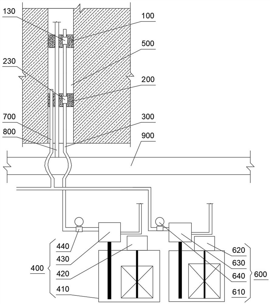
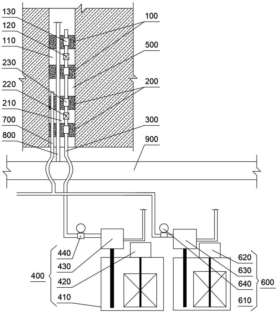
[0030] Such as figure 1 and figure 2 Shown: A sealing system for mine gas drainage, including inner and outer bladder seals, both of which are connected with injection valves. The grout pipe, the grouting equipment supplies the grouting fluid to the inner and outer bladder seals through the grout pipe; an intermediate seal is formed between the inner bladder seal and the outer bladder seal. For the mucus plugging sect...


PUM


Abstract

The invention provides a mining gas extraction hole sealing system, which belongs to the technical field of mining hole sealing, and comprises an inner side bag type plug and an outer side bag type plug, and grouting liquid pipes are arranged in the inner side bag type plug and the outer side bag type plug in a communicating manner; the grouting equipment provides grouting liquid for the inner bag type plug and the outer bag type plug through a grouting liquid pipe; a middle mucus plugging section is formed between the inner-side bag type plugging part and the outer-side bag type plugging part, mucus injection equipment injects mucus into the middle mucus plugging section through a mucus injection pipe, and continuous pressure maintaining is carried out; according to the invention, the two ends are plugged by adopting the bags into which the slurry can be injected, the middle mucus plugging section is formed between the bags at the two ends, the non-solidified mucus is injected into the middle mucus plugging section, and meanwhile, the mucus can be supplemented in time when the pressure of the middle mucus plugging section is reduced so as to keep a certain pressure; therefore, the drilling hole sealing effect is guaranteed, the gas extraction concentration and efficiency are improved, and safe production of a coal mine is guaranteed.

Description

technical field [0001] The invention relates to the technical field of hole sealing for mines, in particular to a hole sealing system for mining gas drainage. Background technique [0002] At present, the "two blocks and one injection" sealing process is as follows: the grouting type (pressurized) hole sealing device for gas drainage of the bag is mainly composed of a grouting pipe, a gas drainage pipe, a one-way valve, a blasting valve, a bag, Plugs etc. The grouting pipe of the hole sealer is connected with the grouting pump, and the grouting liquid stirred in the mixing tank enters the grouting pipe and the bladder through the grouting pump, and the bladder expands rapidly, and the outer diameter of the bladder is fastened to the coal seam. On the hole wall, the holes at both ends of the hole sealer are closed; when the pressure reaches, the blasting valve explodes, and the grouting fluid fills the middle part of the two bladders, thereby realizing multi-layer sealing, a...

Claims


Application Information

Patent Timeline
IPC IPC(8): E21B33/03E21B33/068E21F7/00
Inventor 王兆丰张建国范付恒何艳杰杨晓康王怀生
Owner PINGDINGSHAN ANTAIHUA MINING SAFETY EQUIP MFG
Learn More