Centrifugal fan with flow and temperature adjusting function

A centrifugal fan and temperature adjustment technology, which is applied to the components, electromechanical devices, mechanical equipment, etc. of the pumping device for elastic fluid, which can solve the problems of huge cost, occupying site space, and limited frequency conversion range of variable frequency motors, and achieve high efficiency. High, low pressure loss, widening the effect of flow adjustment range

Inactive Publication Date: 2022-04-12
南京深度系统工程有限公司
View PDF14 Cites 2 Cited by
  • Summary
  • Abstract
  • Description
  • Claims
  • Application Information

AI Technical Summary

Problems solved by technology

[0003] At present, the operation of the flow centrifugal fan relies on the rotation of the frequency conversion motor to drive the impeller to rotate to provide wind pressure, but the frequency conversion range of the frequency conversion motor is limited, and it is difficult to rely on the output of the frequency conversion motor to achieve the required flow demand in the low flow section, so that the ideal flow cannot be obtained. environment; in addition, in the process of driving the fluid, the fan does work on the fluid and the motor itself generates heat, which causes the temperature of the fluid to rise. If you want to obtain the ideal fluid value, you often need a separate refrigeration device to cool the fluid, which not only takes up site space, and cost more

Method used


Image

  • Centrifugal fan with flow and temperature adjusting function
  • Centrifugal fan with flow and temperature adjusting function
  • Centrifugal fan with flow and temperature adjusting function

Examples


Embodiment 1

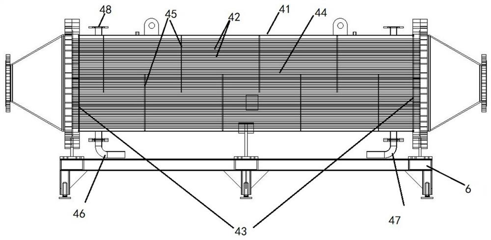
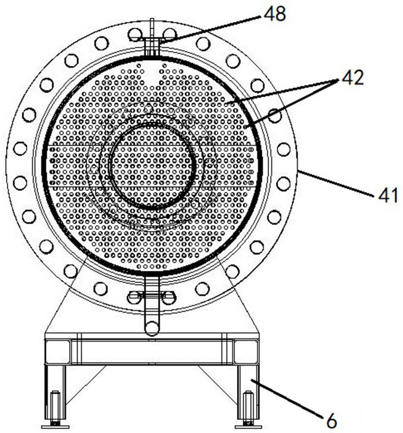
[0026] Example 1, such as Figure 1-5 As shown, a centrifugal fan with flow rate and temperature adjustment includes a centrifugal fan with a fan air inlet 11 and a fan outlet 12, including a volute 21 embedded in the fan housing 13, a centrifugal impeller 22, and a variable frequency motor 23, The centrifugal impeller 22 is placed inside the volute 21, the variable frequency motor 23 is placed in the motor housing 24, and the rotating shaft of the variable frequency motor 23 is coaxial with the centrifugal impeller 22 and connected to each other; the volute 21 includes a volute air inlet 211, a volute air outlet 212, the air inlet of the volute is connected with the air inlet 11 of the fan, the air outlet 212 of the volute is connected with the air outlet 12 of the fan, the air inlet end of the fan housing 13 is provided with an inlet end cover plate 31, and the air outlet end is provided with an outlet end cover plate 32, The temperature adjustment device 4 that adjusts the ...

Embodiment 2

[0041] Example 2, such as Figure 7 , the flow regulating device 5 is arranged on the same vertical plane as the variable frequency motor 23, the flow regulating device 5 includes an annular baffle 71 that seals the motor housing 24 and the fan housing 13, and the annular baffles 71 are arranged in a staggered position and set in the staggered position The flow opening 72 is provided with an adjustment base 51 on the side of the inner flow opening 72, and also includes an adjustment baffle 52 clamped on the adjustment base 51 and connected to the adjustment base 51 through a slide rail, and driving the adjustment baffle 52 sliding adjustment electronic control unit; the adjustment electronic control unit includes a motor 54 placed outside the fan housing 13, the motor 54 is used to drive the transmission shaft 55 that passes through the fan housing 13 and penetrates into the inside of the fan, and the transmission shaft The end of 55 is provided with gear 56, and the bar-shape...


PUM


Abstract

The invention provides a centrifugal fan with flow and temperature regulation, which is characterized in that a temperature regulation device for regulating the temperature of fluid in the centrifugal fan in a coolant heat exchange manner is arranged at an air outlet of the fan, and the temperature regulation device is arranged in the fan or at an air inlet of the fan or at the air outlet of the fan; the flow adjusting device capable of adjusting the actual flowing-through flow by adjusting the actual flowing-through area of the fluid is arranged in a mode of sealing the flowing-through area of the fluid, and the flow adjusting device is combined with the variable frequency motor for use, so that the flow adjusting range of the centrifugal fan, especially the low-frequency adjusting range, can be effectively widened; the flow of the fan can be further reduced by reducing the actual flowing area of fluid, and ideal air pressure is obtained; the temperature adjusting device for adjusting the temperature of fluid in the centrifugal fan in a coolant heat exchange mode is arranged at the air outlet of the fan, air discharged from the fan can be directly cooled, the fluid does not need to be cooled independently, and convenience and high efficiency are achieved.

Description

technical field [0001] The invention relates to the field of gas fluid measurement and verification, in particular to a centrifugal fan with flow and temperature regulation. Background technique [0002] In order to realize the verification of flowmeters under different temperature, pressure and medium conditions, special high-pressure gas flow verification devices are required. Taking natural gas as an example, the verification is usually achieved by cutting off the long-distance natural gas pipeline and then adjusting the pressure, temperature and flow. However, in the actual operation process, due to the impact of high-pressure natural gas station safety, environment, production scheduling, etc., the implementation cost is very high, and the investment in conventional natural gas real-flow verification stations is too high. Hundreds of millions of yuan, and the implementation of the detection process is also difficult. Using the high-pressure loop gas flow verification d...

Claims


Application Information

Patent Timeline
Patent Type & Authority Applications(China)
IPC IPC(8): F04D25/08F04D27/00F04D29/42F04D29/58H02K9/06
Inventor 林亮
Owner 南京深度系统工程有限公司
Why Eureka
Try Eureka