Supercharge Your Innovation With Domain-Expert AI Agents!

Hydraulic shunting synchronous surveying mechanism

A hydraulic and mounting column technology, which is applied in fluid pressure actuation system testing, mechanical equipment, fluid pressure actuation devices, etc., can solve problems such as lack of flexibility and lower detection efficiency, and achieve the effect of enhancing flexibility

Pending Publication Date: 2022-04-12
王大云
View PDF0 Cites 0 Cited by
  • Summary
  • Abstract
  • Description
  • Claims
  • Application Information

AI Technical Summary

Problems solved by technology

[0004] The purpose of the present invention is to provide a hydraulic shunt synchronous survey mechanism to solve the problem that many current survey mechanisms lack flexibility in use and need to be manually supported by the survey mechanism, which greatly reduces the detection efficiency.

Method used


Image

  • Hydraulic shunting synchronous surveying mechanism
  • Hydraulic shunting synchronous surveying mechanism
  • Hydraulic shunting synchronous surveying mechanism

Examples


Embodiment Construction

[0030] In order to make the purpose, technical solutions and advantages of the embodiments of the present invention clearer, the technical solutions in the embodiments of the present invention will be clearly and completely described below in conjunction with the drawings in the embodiments of the present invention. Obviously, the described embodiments It is a part of embodiments of the present invention, but not all embodiments. The components of the embodiments of the invention generally described and illustrated in the figures herein may be arranged and designed in a variety of different configurations.

[0031] Accordingly, the following detailed description of the embodiments of the invention provided in the accompanying drawings is not intended to limit the scope of the claimed invention, but merely represents selected embodiments of the invention. Based on the embodiments of the present invention, all other embodiments obtained by persons of ordinary skill in the art wi...


PUM


Abstract

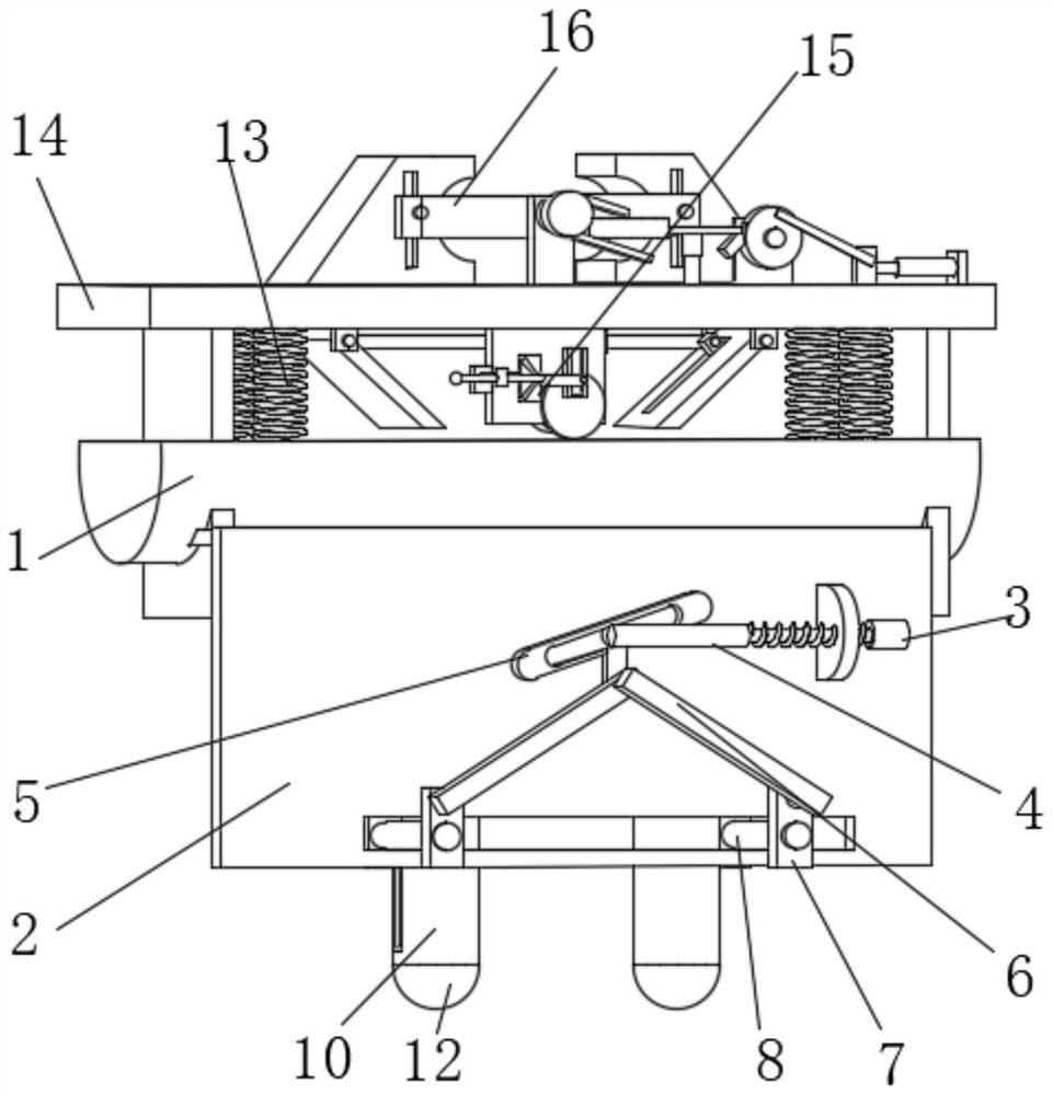
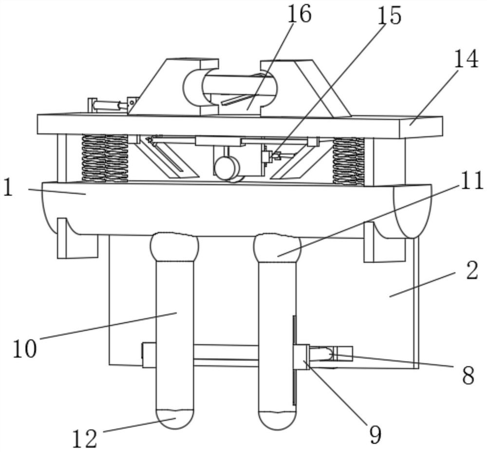
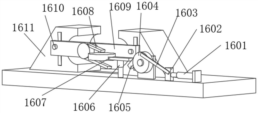
The invention provides a hydraulic shunting synchronous surveying mechanism, and belongs to the field of hydraulic shunting surveying, the hydraulic shunting synchronous surveying mechanism comprises a mounting column, a limiting plate, a sliding plate, a mounting rod and a connecting ball, the bottom of the mounting column is fixedly connected with a mounting plate, and the surface of the mounting plate is provided with a screw rod; the tail of the lead screw is rotationally connected with a push rod driving the limiting plate to descend along the mounting plate, the surface of the limiting plate is rotationally connected with a first movable plate driving the sliding plate to transversely slide on the surface of the mounting plate, and the surface of the sliding plate is fixedly connected with a first sliding rod. According to the hydraulic shunting synchronous surveying mechanism, by arranging an embedded rod, the embedded rod is arranged in a slide way on the surface of a second sliding block, when a moving plate rotates, the second sliding block can be driven to move towards the center line of a connecting plate, a rod can be conveniently clamped through the two sets of second sliding blocks, the detection equipment is fixed, manual supporting is not needed, and the detection efficiency is improved. And the working efficiency of the equipment in use is greatly improved.

Description

technical field [0001] The invention relates to the field of hydraulic diversion survey, in particular to a hydraulic diversion synchronous survey mechanism. Background technique [0002] Hydraulic pressure is a term used in the machinery industry and electromechanical industry. Hydraulic pressure can be used as power transmission to become hydraulic transmission; hydraulic pressure can also be used as a control method called hydraulic control. The hydraulic shunt adopts a flexible and efficient way to combine multiple hydraulic pumps. Together, they are used in multi-circuit hydraulic systems; each splitter includes a series of gear pairs, which divide the input oil into several outputs in equal or proportional proportions, and the working pressure of each channel can be different from each other, and each channel can be Install a safety relief valve. [0003] When the hydraulic shunt is used, it is necessary to survey the hydraulic pressure through the survey mechanism, b...

Claims


Application Information

Patent Timeline
Patent Type & Authority Applications(China)
IPC IPC(8): F15B19/00F15B21/00
Inventor 王大云
Owner 王大云
Features
  • R&D
  • Intellectual Property
  • Life Sciences
  • Materials
  • Tech Scout
  • Unparalleled Data Quality
  • Higher Quality Content
  • 60% Fewer Hallucinations
Learn More