Detection device for planetary gear speed reducer
A planetary gear reduction and detection device technology, applied in the direction of measuring devices, transmission parts, gear lubrication/cooling, etc., can solve the problems of damage, time-consuming and labor-intensive reducers, etc., to reduce damage, reduce manual inspection, and avoid damage. Effect
- Summary
- Abstract
- Description
- Claims
- Application Information
AI Technical Summary
Problems solved by technology
Method used
Image

Examples
Embodiment 1
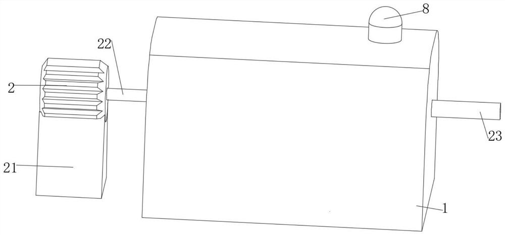
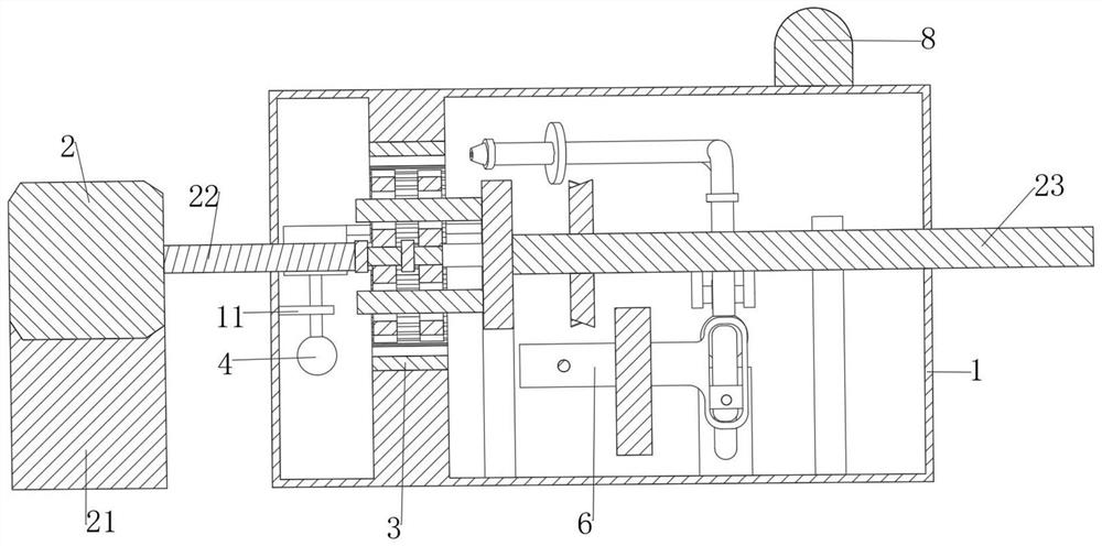
[0031] The invention provides a technical solution: a detection device for a planetary gear reducer, including a reducer housing 1, a motor frame 21, a motor 2, an input shaft 22, a reducer 3, an output shaft 23, an alarm 8, and a motor frame 21 is fixedly connected with the motor 2, the output end of the motor 2 is fixedly connected with the input shaft 22 which runs through the reducer housing 1, the end of the input shaft 22 far away from the motor 2 is connected with the reducer 3, and the end of the reducer 3 is far away from the input shaft 22 It is transmission connected with the output shaft 23 that runs through the reducer housing 1, the reducer housing 1 is fixedly connected with the alarm 8, the inner wall of the reducer housing 1 is fixedly connected with a first support plate 11, and the first support plate 11 is provided with There is an oil detection mechanism for detecting the amount of lubricating oil in the reducer housing 1 , and the reducer housing 1 is prov...
Embodiment 2
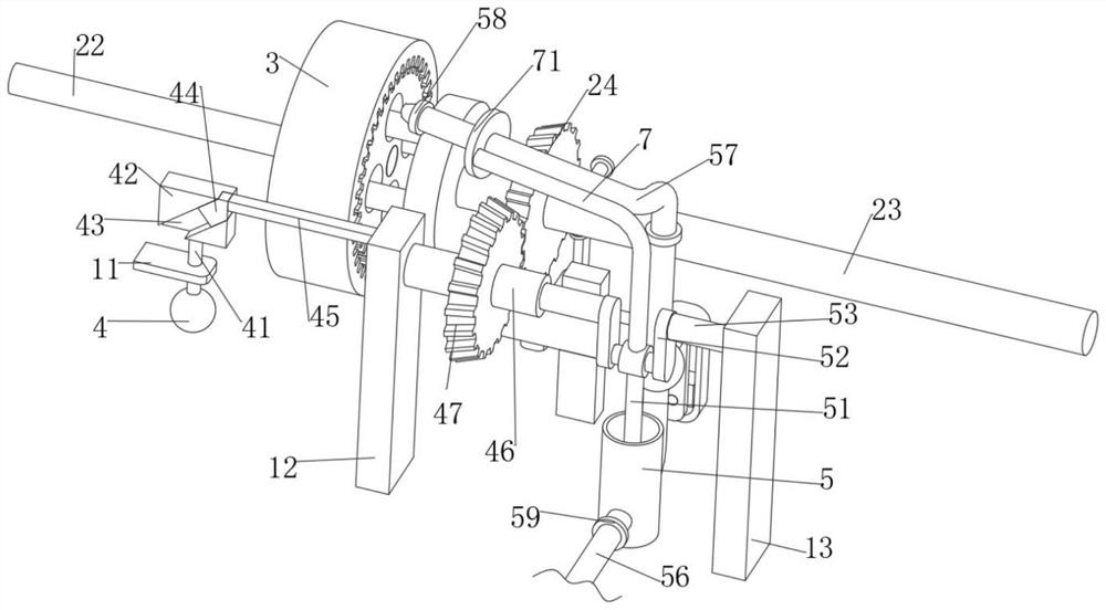
[0043] It is basically the same as the first embodiment, furthermore, the support rod 72 is provided with a cleaner moving mechanism for the movable spraying of the nozzle 58 to wash the iron filings on the reducer 3, and the moving mechanism includes a fixed connection on the support The second connecting rod 7 on the rod 72 is fixedly connected with a connecting plate 71 , and the connecting plate 71 is fixedly connected with the drain pipe 57 .
[0044] When the joint between the piston rod 51 and the support rod 72 rotates, the second connecting rod 7 on it rotates accordingly, so that the connecting plate 71 drives the drain pipe 57 and the spray head 58 to rotate synchronously, achieving multi-directional oil spraying and flushing. Cleaner effect of chip flushing on reducer 3.
Embodiment 3
[0046] It is basically the same as the second embodiment, furthermore, the reducer housing 1 is provided with a collection mechanism for collecting iron filings, the collection mechanism includes a ball joint 77 fixedly connected to the drain pipe 57, and the ball joint 77 is A through hole is opened and a second rotating rod 74 is fixedly connected to the shaft through the through hole. The second rotating rod 74 is fixedly connected with the impeller 73 located in the spherical joint 77. The second crank 75 is fixedly connected with a pin shaft, and the second crank 75 is rotatably connected with a slider 76 through the pin shaft.
[0047] Further, the collection mechanism also includes a fourth support plate 14 fixedly connected in the reducer housing 1, a chute is opened on the fourth support plate 14, and a T-shaped slider 6 is slidably connected to the chute through the chute. , the T-shaped slider 6 is provided with a chute and is slidably connected with the slider 76 t...
PUM
 Abstract
Description
Claims
Application Information
 - R&D
- Intellectual Property
- Life Sciences
- Materials
- Tech Scout
- Unparalleled Data Quality
- Higher Quality Content
- 60% Fewer Hallucinations
Browse by: Latest US Patents, China's latest patents, Technical Efficacy Thesaurus, Application Domain, Technology Topic, Popular Technical Reports.
© 2025 PatSnap. All rights reserved.Legal|Privacy policy|Modern Slavery Act Transparency Statement|Sitemap|About US| Contact US: help@patsnap.com