Natural lighting system

A technology of natural light lighting and light, applied in the direction of light guide, lighting application, lighting device of lighting system, etc., can solve the problems of weak light intensity, easy to be damaged, natural light lighting system cannot enhance light intensity, etc., to meet the requirements of light transmittance Effect

Pending Publication Date: 2022-04-12
安珊瑞娜
View PDF12 Cites 0 Cited by
  • Summary
  • Abstract
  • Description
  • Claims
  • Application Information

AI Technical Summary

Problems solved by technology

[0005] 1. When the natural light lighting system is installed in a multi-storey building, its light-guiding fiber will often be split. When splitting, the light will be attenuated at the joint. At the same time, the fiber split will make the diameter of the split fiber smaller than the main fiber. It will inevitably lead to the weakening of the light intensity in each bundle of optical fibers, which will eventually lead to poor lighting effect at the end;
[0006] 2. When the natural light intensity is strong, the natural light lighting system cannot reduce the light intensity; when the natural light intensity is weak, the natural light lighting system cannot increase the light intensity, that is, the light intensity cannot be adjusted by artificial means;
[0007] 3. When the natural light is weak during the day, traditional lighting methods are still needed for supplementary lighting, that is, the system lacks more energy-saving supplementary light means;
[0008] 4. When bad weather occurs, the receiving natural light end of the natural light lighting system is exposed and easily damaged

Method used


Image

  • Natural lighting system
  • Natural lighting system
  • Natural lighting system

Examples


Embodiment 1

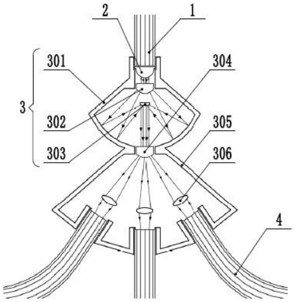
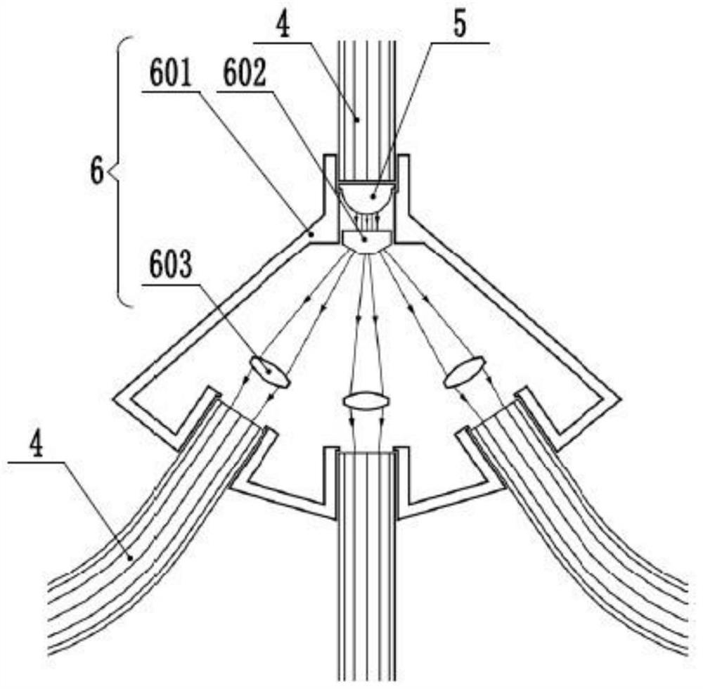
[0083] Such as figure 1 As shown in -27, the natural light lighting system provided by the present invention includes a light concentrating device 17 arranged at a position capable of receiving natural light, and also includes head-end light enhancing light splitters connected to the light concentrating device 17 and arranged sequentially from top to bottom. Device 3, head splitting connector 6, mid-end optical fiber enhanced splitting device 8, mid-end splitting connector 11, end splitting connector 13 and optical fiber special lighting equipment 19;

[0084] A first-class optical fiber 1 is connected between the head-end light-enhanced spectroscopic device 3 and the light-transmitting hole, and a first-class condenser lens 2 is arranged at the connection between the two; The mid-end optical fiber enhanced splitting device 8, the mid-end splitting connector 11 and the end splitting connector 13 are all connected with a secondary optical fiber 4, and the connections are respec...

Embodiment 2

[0112] This embodiment is basically the same as Embodiment 1 and the only difference is:

[0113] Such as Figure 17 As shown, in this embodiment, the condensing device 17 includes a second condensing bowl and a reflector arranged on the focal point of the second condensing bowl, and a light-transmitting hole is opened in the middle of the bottom of the second condensing bowl;

[0114] A primary light intensity adjustment device is arranged directly above the light concentrating device 17;

[0115] The primary light intensity adjusting device comprises an iris light adjusting device 14 and a solar light enhancing device 15 arranged directly below the iris light adjusting device 14;

[0116] Such as Figure 18 — Figure 23 As shown, the iris light adjusting device 14 includes an iris base 1401, an iris cover 1407 and a first motor 1405, and a number of circumferentially arranged shading blades 1404 are rotatably connected between the iris base 1401 and the iris cover 1407, ...

Embodiment 3

[0136] This embodiment is basically the same as Embodiment 1 and the only difference is:

[0137] In this example, if Figure 12 As shown, the inner walls of the first focusing bowl 1710 and the second focusing bowl are provided with several triangular reflectors 1713 arranged in an arc as a whole.


PUM


Abstract

The invention relates to the technical field of natural lighting equipment, in particular to a natural lighting system. The head-end light-enhancing light-splitting device, the head-end light-splitting connector, the middle-end optical-fiber-enhancing light-splitting device, the middle-end light-splitting connector and the tail-end light-splitting connector are arranged, light is condensed and enhanced when optical fibers are split, and attenuation of the light is avoided; the iris light adjusting device is arranged to adjust the illumination intensity, when the natural illumination intensity is larger than the needed illumination intensity, only the shading blades need to be opened, so that the light gathering device receives less natural light, and otherwise, the shading blades are folded; the solar light enhancing device is arranged, so that energy-saving auxiliary light supplement can be carried out, and when natural light is weak, light supplement of the light condensing device can be achieved by turning on the annular lamp strip; the iris light adjusting device and the solar light enhancing device can be completely closed, and when the weather condition is poor, the iris light adjusting device and the solar light enhancing device can be completely closed to protect the light condensing device and avoid natural damage such as rainwater erosion.

Description

technical field [0001] The invention relates to the technical field of natural light lighting equipment, in particular to a natural light lighting system. Background technique [0002] Many buildings also need lighting during the day, such as schools, office buildings, tunnels, subway stations, etc. At present, most of the above-mentioned buildings use the traditional way of electric lighting, and the power required for lighting is huge. [0003] In order to reduce the power consumption required for lighting, many natural light auxiliary lighting systems are currently designed in China, such as the Chinese invention patent with the authorized announcement number CN107504451B: a passive natural light omnidirectional collection device and collection method. The collection device includes a 180° hemisphere A lens array with a shape distribution, each lens focal point in the lens array is equipped with a light-guiding fiber, and all the light-guiding fibers form a fiber array co...

Claims


Application Information

Patent Timeline
Patent Type & Authority Applications(China)
IPC IPC(8): F21S19/00F21S9/03F21V14/00F21V14/04F21V15/00F21V8/00F21Y115/10
CPCY02B10/10
Inventor 安珊瑞娜
Owner 安珊瑞娜
Why Eureka
Try Eureka