Industrial dehumidifier with high dehumidification efficiency
A dehumidifier and efficiency technology, applied in the field of industrial dehumidifiers, can solve the problems of slow dehumidification effect, affecting dehumidification efficiency, and short-circuiting of the dehumidification space, so as to shorten the dehumidification time, improve the dehumidification efficiency, and have a wide recyclable space. Effect
- Summary
- Abstract
- Description
- Claims
- Application Information
AI Technical Summary
Problems solved by technology
Method used
Image
Examples
Embodiment 1
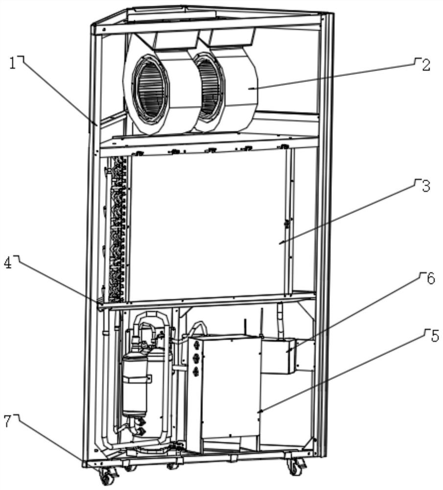
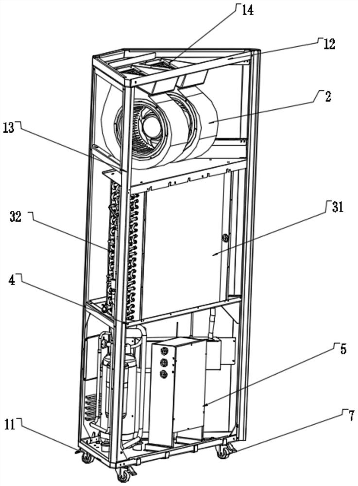
[0042] refer to Figure 1-Figure 4 , is an industrial dehumidifier with high dehumidification efficiency disclosed by the present invention, comprising a housing 1, an air supply system 2 and a dehumidification system 3, the air supply system 2 and the dehumidification system 3 are installed inside the housing 1, and the air supply The air system 2 is located above the dehumidification system 3. Driven by the air supply system 2, the external humid air is sucked out of the equipment, and then passed through the dehumidification system 3 for drying, and the dry air is sent out in time through the air supply system 2. Exhaust, the housing 1 includes a chassis 11, a top cover 12 and a frame 13, the top cover 12 and the chassis 11 are respectively located at the upper and lower ends of the frame 13, the surface of the top cover 12 is provided with an air outlet 14 communicating with the air supply system 2, There is at least one air outlet 14, and the air discharged through the ai...
Embodiment 2
[0048] refer to Figure 5 The difference between this embodiment and Embodiment 1 is that the air supply system 2 is vertically arranged, and the top cover 12 is obliquely installed above the frame 13. In this embodiment, the fan of the air supply system 2 can be a standard fan, only The casing 1 needs to be adjusted, and the top cover 12 is inclined to ensure that the air from the air outlet 14 is discharged obliquely upward.
Embodiment 3
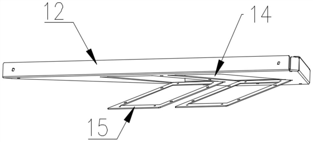
[0050] refer to Figure 6 , the difference between this embodiment and Embodiment 1 is that the output end of the air supply system 2 communicates with the outside through the air outlet 14, and is arranged obliquely above the air outlet 14. The surface of 12 offers connecting portion 15, directly modifies the shape of the air outlet of blower fan, and runs through air outlet 14 to release air obliquely upwards, easy to use.
PUM
 Abstract
Description
Claims
Application Information
 - R&D Engineer
- R&D Manager
- IP Professional
- Industry Leading Data Capabilities
- Powerful AI technology
- Patent DNA Extraction
Browse by: Latest US Patents, China's latest patents, Technical Efficacy Thesaurus, Application Domain, Technology Topic, Popular Technical Reports.
© 2024 PatSnap. All rights reserved.Legal|Privacy policy|Modern Slavery Act Transparency Statement|Sitemap|About US| Contact US: help@patsnap.com


