
Sample fatigue tension and compression loading test device and installation method

A technology of loading test device and installation method, which is applied in the direction of measuring device, application of repeated force/pulsation force to test material strength, instrument, etc., can solve problems such as thread gap and test failure, and achieve resonance, installation and operation, and convenience The effect of the operation

Pending Publication Date: 2022-04-12
DONGFENG MOTOR GRP
View PDF9 Cites 0 Cited by
  • Summary
  • Abstract
  • Description
  • Claims
  • Application Information

AI Technical Summary

Problems solved by technology

The fixture introduced in this patent can eliminate the thread gap to a certain extent, but only when the sample bears the tension force. When the sample starts to bear the compression force, due to the applied compression force and the bearing circle Whether the force exerted by the disc on the sample is opposite, or it may cause a thread gap between the pressure-bearing disc and the sample, especially when performing a tensile-compression load test, it is very easy to have a thread gap that leads to the failure of the test. fail

Method used


Image

  • Sample fatigue tension and compression loading test device and installation method
  • Sample fatigue tension and compression loading test device and installation method
  • Sample fatigue tension and compression loading test device and installation method

Examples


Embodiment Construction

[0039]Embodiments of the present invention are described in detail below, wherein the same or similar reference numerals represent the same or similar elements or elements having the same or similar functions. The embodiments described below by referring to the figures are exemplary and are intended to explain the present invention and should not be construed as limiting the present invention.

[0040] In describing the present invention, it should be understood that the terms "longitudinal", "transverse", "length", "width", "thickness", "upper", "lower", "front", "rear", " The orientation or positional relationship indicated by "left", "right", "vertical", "horizontal", "top", "bottom", "inner" and "outer" are based on the orientation or positional relationship shown in the drawings, and only It is for the convenience of describing the present invention and simplifying the description, but does not indicate or imply that the referred device or element must have a specific ori...


PUM


Abstract

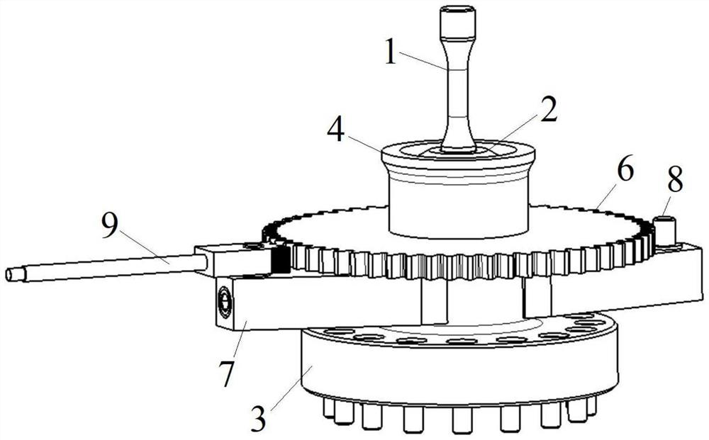
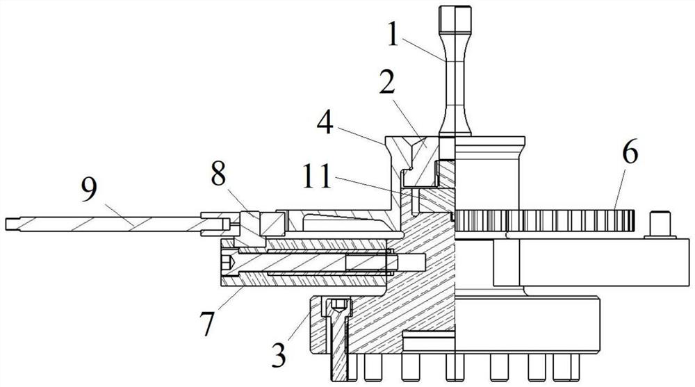
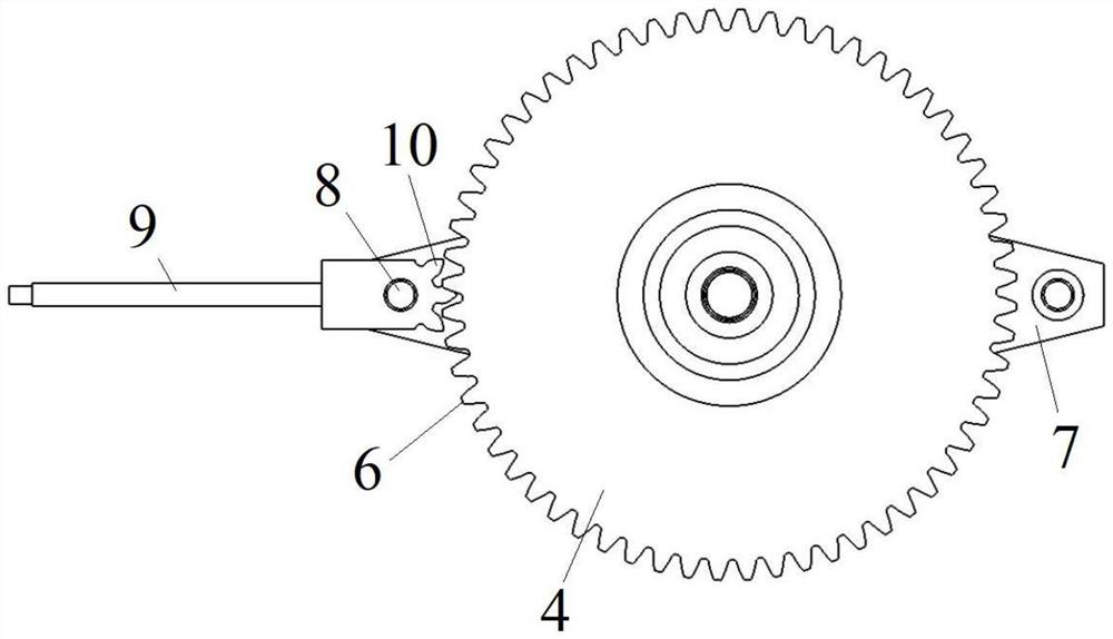
The invention relates to the technical field of metal material fatigue performance test device structures, in particular to a sample fatigue tension and compression loading test device and an installation method. Comprising a sample connecting flange table and an annular structure which sleeves the outer side of the circumference of a sample and is in external thread connection with the outer side of the circumference of the sample, one end of the testing machine connecting flange table is connected with the testing machine, and the other end abuts against the axial end of the sample and is used for transmitting load to the sample; the pressing structure is used for driving the sample connecting flange table to press towards one side of the testing machine connecting flange table, so that the axial end part of the sample is tightly propped against the testing machine connecting flange table, and a thread gap between the sample and the sample connecting flange table is eliminated. The test device is simple in structure and convenient to operate, can well eliminate thread gaps between the sample and all parts, increases the connection rigidity between the sample and all the parts, ensures the resonance of a resonance system of the fatigue testing machine, and has great popularization value.

Description

technical field [0001] The invention relates to the structural technical field of a metal material fatigue performance test device, in particular to a sample fatigue tensile and compressive loading test device and an installation method. Background technique [0002] When material samples are subjected to high-cycle fatigue tests, in order to shorten the test period and save test costs, they are usually tested on high-frequency fatigue testing machines. The high-frequency fatigue testing machine applies a high-frequency load to the sample through the resonance generated between the sample, the fixture, and the resonance system for fatigue testing. The high-frequency fatigue testing machine requires a rigid connection between the sample and the fixture without any gaps, otherwise the resonance of the testing machine will be affected and the test cannot be performed. [0003] Before the fatigue test, both ends of the sample need to be clamped and fixed, and a fatigue load is ...

Claims


Application Information

Patent Timeline
Patent Type & Authority Applications(China)
IPC IPC(8): G01N3/04G01N3/32
Inventor 刘玉龙黄文长李万江
Owner DONGFENG MOTOR GRP
Learn More