Multi-view static CT system

A multi-view, static technology, applied in the field of radiation imaging, can solve the problems of heavy equipment volume and increase weight load, etc., to achieve the effect of reducing equipment cost, simplifying equipment structure, and simple structure

Pending Publication Date: 2022-04-12
BEIJING HANGXING MACHINERY MFG CO LTD
View PDF4 Cites 0 Cited by
  • Summary
  • Abstract
  • Description
  • Claims
  • Application Information

AI Technical Summary

Problems solved by technology

[0006] In view of the above analysis, the present invention aims to provide a multi-view static CT system to solve the problem that the existing static CT equipment needs to add additional weight load in order to maintain the overall stability, resulting in heavy equipment and too large volume

Method used


Image

  • Multi-view static CT system
  • Multi-view static CT system
  • Multi-view static CT system

Examples


Embodiment 1

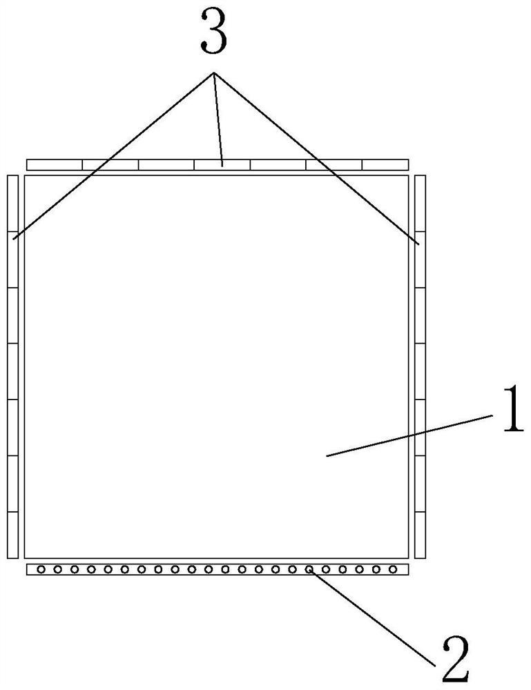
[0051] see figure 1 , the imaging unit in this embodiment includes a plurality of radiation sources 2 arranged on the periphery of the delivery channel 1, the outer shape of the delivery channel 1 is specifically a square, the radiation source 2 includes a plurality of focal points, and the plurality of focal points are arranged continuously along a straight line. The ray source 2 is specifically arranged at the bottom of the transport channel 1 to form an imaging unit at a low viewing angle.

[0052] The detector assembly includes a detector 3 . Specifically, the detector 3 includes three sets of detectors arranged on the top and both sides of the transport channel 1, the ray source 2 and the three sets of detectors are arranged on a plane parallel to the X-Y plane, and the formed imaging plane is perpendicular to the transport of the object. direction. The three groups of detectors 3 are arranged along the folded lines and arranged opposite to the radiation source 2, formi...

Embodiment 2

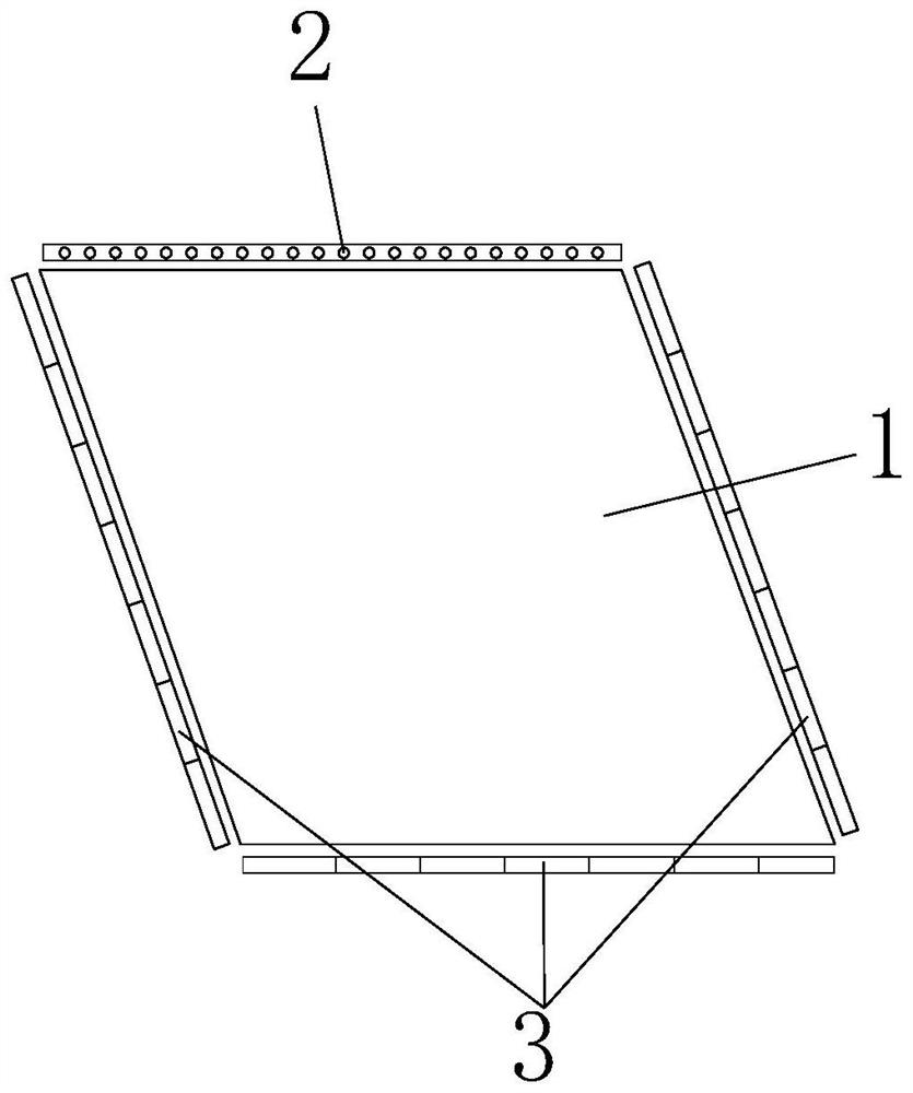
[0055] see figure 2 , the imaging unit in this embodiment includes a plurality of radiation sources 2 arranged on the periphery of the delivery channel 1, the outer shape of the delivery channel 1 is specifically a square, the radiation source 2 includes a plurality of focal points, and the plurality of focal points are arranged continuously along a straight line. The ray source 2 is specifically arranged on the top of the transport channel 1 to form an imaging unit under the top view.

[0056] The detector assembly includes a detector 3 . Specifically, the detector 3 includes three sets of detectors arranged at the bottom and side of the transport channel 1, the radiation source 2 and the three sets of detectors 3 are arranged on an imaging plane, and the formed imaging plane is not perpendicular to the transporting direction of the object , that is, there is an angle between the imaging plane formed by the ray source 2 and the three sets of detectors and the X-Y plane. Th...

Embodiment 3

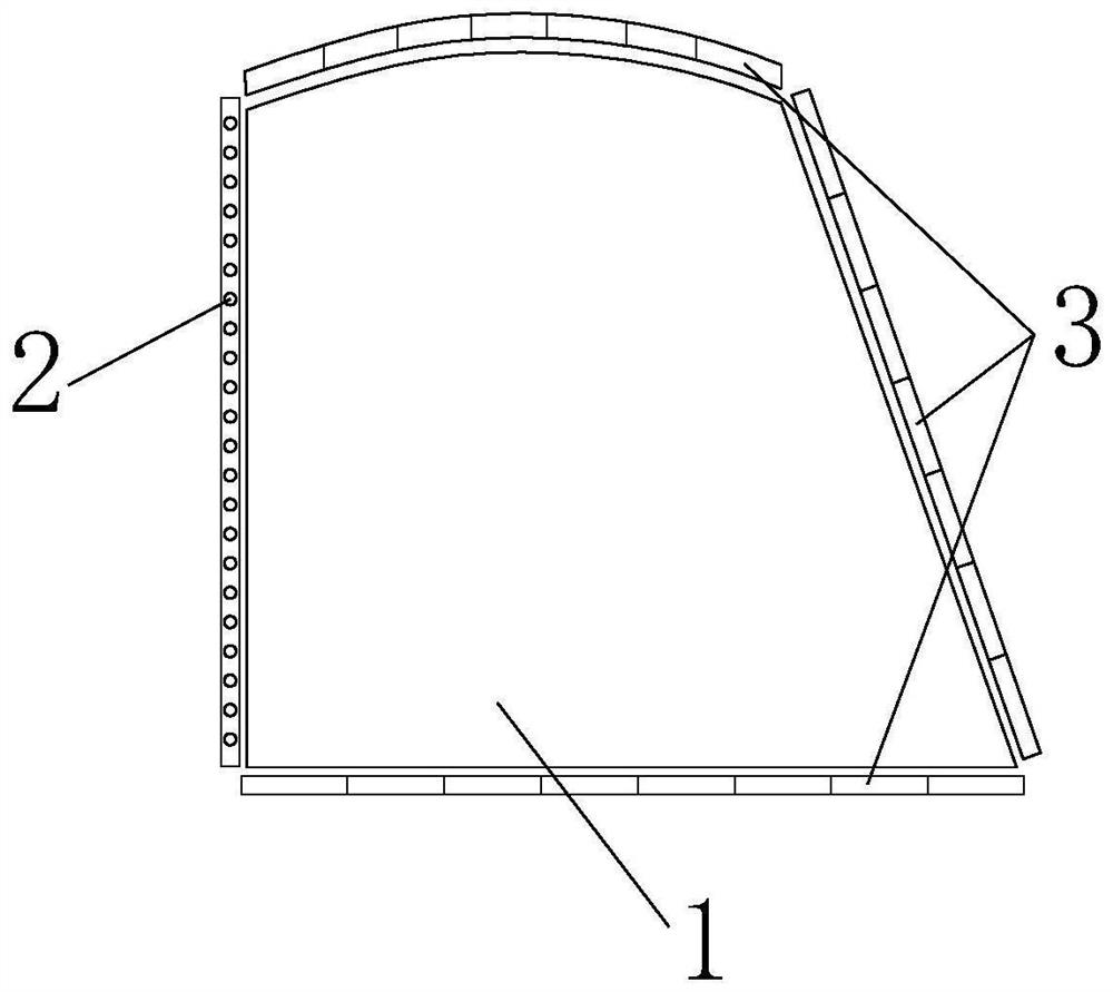
[0059] see image 3 , the imaging unit in this embodiment includes a plurality of radiation sources 2 arranged on the periphery of the delivery channel 1, the outer shape of the delivery channel 1 is specifically a dome shape, the radiation source 2 includes a plurality of focal points, and the plurality of focal points are arranged continuously along a straight line . The ray source 2 is specifically arranged on the side of the transport channel 1 to form an imaging unit under a side view. In this embodiment, the specific position of the ray source 2 on the side of the transport channel 1 is not limited, and the ray source 2 can be arranged on the object transport The left side of the direction can also be set on the right side of the object conveying direction, both of which can achieve the technical purpose of side view imaging.

[0060] The detector assembly includes a detector 3 . The detector 3 includes three groups of detectors, and the three groups of detectors are r...


PUM


Abstract

The invention relates to a multi-view static CT (Computed Tomography) system, belongs to the technical field of radiation imaging, and solves the problems that the existing static CT equipment needs to increase additional weight load in order to maintain the overall stability, so that the equipment is heavy and the size is too large. A multi-view static CT system includes: a transfer channel; imaging units with different visual angles are arranged in the conveying direction of the object, and the imaging units are arranged on the periphery of the conveying channel; the imaging unit comprises a radiation source and a detector assembly arranged corresponding to the radiation source. The imaging units with different visual angles are arranged in the object conveying direction, and the imaging units are arranged on the periphery of the conveying channel, so that static scanning imaging of the object can be completed in the advancing process of the object in the conveying channel, and CT imaging of the object at different visual angles is guaranteed.

Description

technical field [0001] The invention relates to the technical field of radiation imaging, in particular to a multi-view static CT system. Background technique [0002] Among the X-ray-based explosives inspection technologies, X-ray computed tomography imaging technology (referred to as "CT technology") is highly valued in the field of security inspection due to its own unique advantages. [0003] The current security inspection CT equipment is mainly divided into spiral CT and static CT equipment based on slip ring technology. Spiral CT equipment usually arranges the radiation source and detector on the rotating frame, and solves the problem of continuous rotation of the frame through slip ring technology. Since the centrifugal force experienced by the part increases with the square of the rotation speed, the increase in scanning speed places high demands on the performance of the frame. In addition, the angle accuracy and position accuracy of the gantry during the rotatio...

Claims


Application Information

Patent Timeline
Patent Type & Authority Applications(China)
IPC IPC(8): G01N23/046G01V5/00
Inventor 李保磊魏增辉孙翠丽韩毅莫阳牛素鋆徐圆飞
Owner BEIJING HANGXING MACHINERY MFG CO LTD
Why Eureka
Try Eureka