Heat flow type differential scanning calorimeter
A technology of differential scanning calorimetry and calorimeter, which is applied in the field of thermal analysis instruments, can solve the problems of insufficient sealing effect of the heating chamber, influence of the use of the calorimeter, inconvenient fixing of the calorimeter and shock absorption, etc., to achieve a solution The sealing effect is not good enough to avoid heat loss and the effect of shock absorption is good
- Summary
- Abstract
- Description
- Claims
- Application Information
AI Technical Summary
Problems solved by technology
Method used
Image
Examples
Embodiment 1
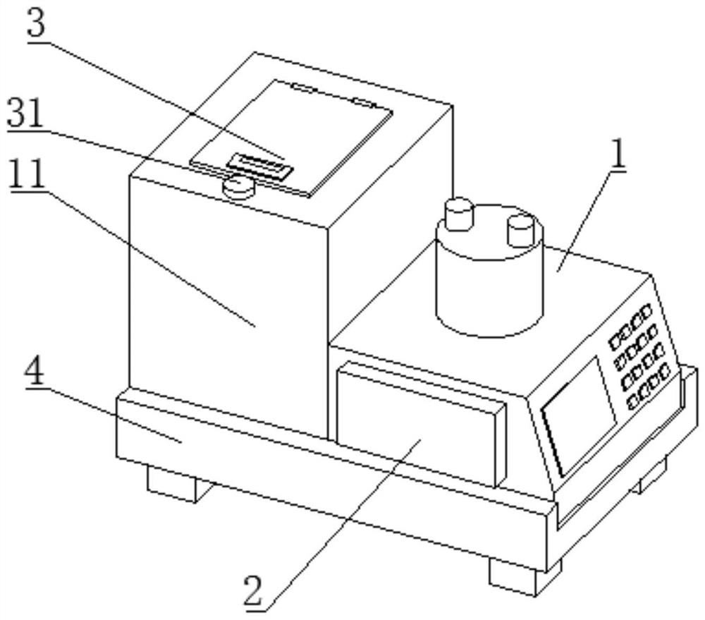
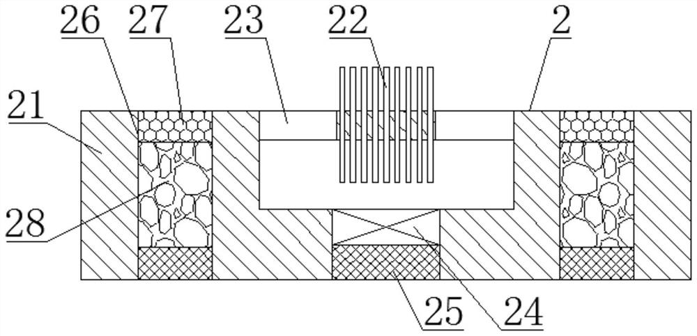
[0040] Such as Figure 1-6As shown, the present invention provides a heat flow type differential scanning calorimeter, comprising a calorimeter body 1 and a heat dissipation mechanism 2, the heat dissipation mechanism 2 is fixedly connected to the left end of the calorimeter body 1, and the side surface of the calorimeter body 1 The heat dissipation mechanism 2 is fixedly connected, the heating chamber door 3 is movably connected to the top of the heating chamber 11, the front end of the heating chamber door 3 is provided with a locking mechanism 31, the bottom end of the calorimeter body 1 is movably connected with a fixing mechanism 4, and the heat dissipation mechanism 2 includes a cooling box 21, the cooling box 21 is fixedly connected to the side of the calorimeter body 1, the top of the cooling box 21 is fixedly connected with a cooling fin 22, the top of the cooling box 21 is provided with an exhaust port 23, and the bottom of the exhaust port 23 The end is provided wit...
Embodiment 2
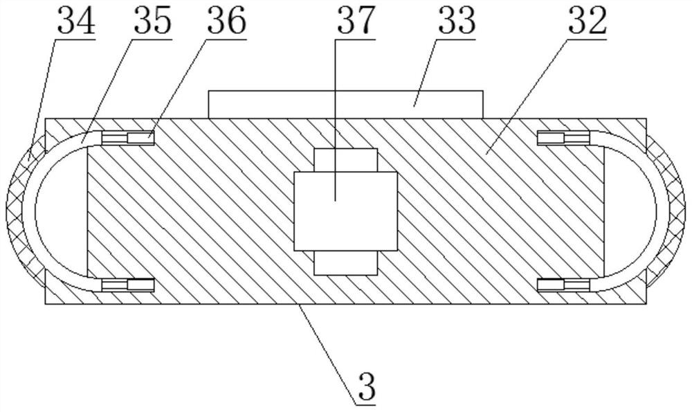
[0043] Such as Figure 1-6 As shown, on the basis of Embodiment 1, the present invention provides a technical solution: preferably, the heating door 3 includes a door panel 32, and the door panel 32 moves on the top of the heating cabin 11, and the top of the door panel 32 Fixedly connected with a handle 33, the side of the handle 33 is fixedly connected with a gasket 34, the inner side of the gasket 34 is provided with an elastic top plate 35, one end of the elastic top plate 35 is fixedly connected with a telescopic rod 36, and one end of the telescopic rod 36 is fixedly connected with the door panel Inside the body 32, the middle part of the door plate body 32 is provided with a locking groove 37, the locking mechanism 31 includes a rotating block 311, the rotating block 311 is arranged on the top of the heating chamber 11, and the bottom end of the rotating block 311 is fixedly connected with a driving wheel 312 , the side of the driving wheel 312 is meshed with a driven w...
Embodiment 3
[0046] Such as Figure 1-6 As shown, on the basis of Embodiment 1, the present invention provides a technical solution: preferably, the fixing mechanism 4 includes a fixed base 41, the fixed base 41 is arranged at the bottom end of the calorimeter body 1, and the inner side of the fixed base 41 is movable Be connected with top block 42, the side of top block 42 is fixedly connected with jacking spring 43, the bottom end of fixed base 41 is provided with damping mechanism 48, the left side of fixed base 41 is provided with driving block 44, and the right end of driving block 44 is fixed A two-way screw 45 is connected, the side of the two-way screw 45 is threadedly connected with a threaded block 46 , and the side of the threaded block 46 is movably connected with a fixed block 47 .
[0047] In this embodiment, the calorimeter body 1 is placed inside the fixed base 41, and the top block 42 is moved by the tightening spring 43, so that the side of the calorimeter body 1 can be f...
PUM
 Abstract
Description
Claims
Application Information
 - R&D
- Intellectual Property
- Life Sciences
- Materials
- Tech Scout
- Unparalleled Data Quality
- Higher Quality Content
- 60% Fewer Hallucinations
Browse by: Latest US Patents, China's latest patents, Technical Efficacy Thesaurus, Application Domain, Technology Topic, Popular Technical Reports.
© 2025 PatSnap. All rights reserved.Legal|Privacy policy|Modern Slavery Act Transparency Statement|Sitemap|About US| Contact US: help@patsnap.com


