
Motor rotation locking system

A technology of rotation locking and rotor, applied in the direction of electromechanical devices, electrical components, electric components, etc., can solve the problems of loss and vibration efficiency, and achieve the effect of solving the problems of vibration and efficiency loss

Active Publication Date: 2022-04-12
NANCHANG SANRUI INTELLIGENT TECH CO LTD
View PDF12 Cites 0 Cited by
  • Summary
  • Abstract
  • Description
  • Claims
  • Application Information

AI Technical Summary

Problems solved by technology

[0003] The problem to be solved by the present invention is to provide a motor rotation locking system, which drives the magnetic group 1 or the magnetic group 2 through the drive assembly to change the distance between the magnetic resistance 1 and the magnetic resistance 2 or the mutual projected overlapping area between the two. It can ensure sufficient locking effect, and solve the vibration and efficiency loss problems caused by the motor operation

Method used


Image

  • Motor rotation locking system
  • Motor rotation locking system
  • Motor rotation locking system

Examples


Embodiment 1

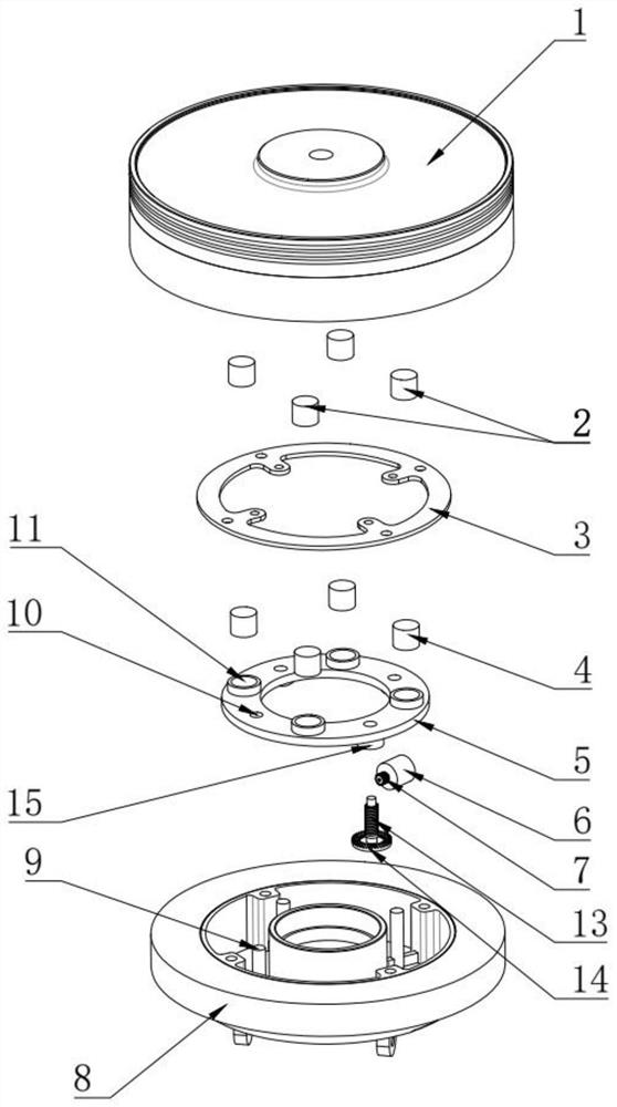
[0032] This example Figure 1-2 As shown, a motor rotation locking system includes a stator 8 and a rotor 1; it also includes a magnetic group 1, a magnetic group 2 and a drive assembly;

[0033] The magnetic group 1 and the magnetic resistance 2 are separately arranged on the stator 8 and the rotor 1;

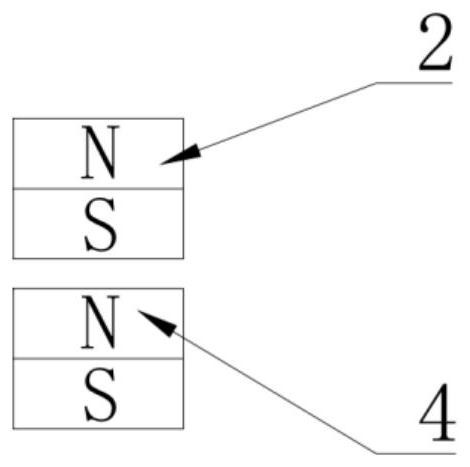
[0034] The driving assembly is used to drive the magnetic group 1 or the magnetic group 2 to change the distance between the first magnetic resistance and the second magnetic resistance or the mutual projected overlapping area between the two.

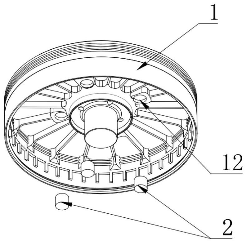
[0035] In this embodiment, the magnetic group one includes four permanent magnets one 2 , and the four permanent magnets one 2 are installed on the rotor 1 .

[0036] Further, the lower part of the rotor 1 is provided with four fixing grooves 12 for accommodating the permanent magnet 2 .

[0037] Further, the fixing groove 12 is provided with a fixing plate 3 . The magnetic group 1 is fixed by the fixed pressure plate, and the seali...

Embodiment 2

[0045] Such as Figure 6-9 As shown, in this embodiment, the drive assembly is used to drive the magnetic group 1 or the magnetic group 2 to change the mutual projected overlapping area between the magnetic resistance 1 and the magnetic resistance 2, wherein the permanent magnet 1 and the permanent magnet The second magnet is arranged in a dislocation, which is different from the up-and-down arrangement in Embodiment 1. The rest of the structure is the same as that in Embodiment 1, and will not be described here.


PUM


Abstract

The invention discloses a motor rotation locking system which comprises a stator and a rotor. The device further comprises a first magnetic group, a second magnetic group and a driving assembly. The first magnetic group and the second magnetic resistor are arranged on the stator and the rotor. The driving assembly is used for driving the first magnetic group or the second magnetic group to change the distance between the first magnetic resistor and the second magnetic resistor or the overlapping area of mutual projection between the first magnetic resistor and the second magnetic resistor. According to the invention, the driving assembly drives the magnetic group I or the magnetic group II to change the distance between the magnetic resistor I and the magnetic resistor II or the overlapping area of mutual projection between the magnetic resistor I and the magnetic resistor II, so that an enough locking effect can be ensured, and the problems of vibration and efficiency loss caused by motor operation are solved.

Description

technical field [0001] The invention relates to the technical field of motors, in particular to a motor rotation locking system. Background technique [0002] At present, there is a solution to lock by arranging permanent magnets on the stator and rotor, but the strength of the magnetism determines the effect of the motor propeller to keep locked, and the vibration effect of the magnetism on the operation of the motor and the loss of the motor are contradictory. , The locking effect is good, but the additional vibration is very large, and the weak magnetism can reduce the vibration effect but cannot completely eradicate it, and the locking effect is much worse. Contents of the invention [0003] The problem to be solved by the present invention is to provide a motor rotation locking system, which drives the magnetic group 1 or the magnetic group 2 through the drive assembly to change the distance between the magnetic resistance 1 and the magnetic resistance 2 or the mutual...

Claims


Application Information

Patent Timeline
Patent Type & Authority Applications(China)
IPC IPC(8): H02K5/24H02K7/116H02K7/06
Inventor 吴奇才黄华秋淦吉昌
Owner NANCHANG SANRUI INTELLIGENT TECH CO LTD
Learn More