Centrifugal impeller optimal design method for preventing vibration localization for happening

An optimized design and centrifugal impeller technology, applied in mechanical equipment, machines/engines, liquid fuel engines, etc., can solve problems affecting the safe and reliable operation of fans, impeller vibration fatigue damage, impeller structure detuning, etc., to achieve safe and reliable long-term operation , reduce vibration and related hazards, and reduce the effect of failure rate

Inactive Publication Date: 2012-03-14
XI AN JIAOTONG UNIV
View PDF3 Cites 10 Cited by
  • Summary
  • Abstract
  • Description
  • Claims
  • Application Information

AI Technical Summary

Problems solved by technology

For a long time, the vibration problem of large-scale and high-speed centrifugal impeller has always affected the safe and reliable operation of the fan. Once a problem occurs during operation, the production will be interrupted, causing economic losses;
In addition, due to manufacturing errors in the welding process, the characteristics of the cyclically symmetrical structure of the impeller are often destroyed, resulting in structural detuning, resulting in localized vibration of the impeller, resulting in greater dynamic stress in certain parts, which in turn leads to impeller Accidents caused by vibration fatigue damage

Method used


Image

  • Centrifugal impeller optimal design method for preventing vibration localization for happening
  • Centrifugal impeller optimal design method for preventing vibration localization for happening
  • Centrifugal impeller optimal design method for preventing vibration localization for happening

Examples


example

[0090] Example: a centrifugal impeller

[0091] Fault phenomenon: Cracks appear at the inlet ring of the impeller cover

[0092] Elimination method: adjust the number of blades of the inlet reflux to Z=14

[0093] The main dimensions and technical parameters of the impeller: diameter D = Φ1020mm, number of blades Z = 19, blade thickness δ = 8mm, working speed n = 5545r / min, material: alloy steel, yield limit σ s =8.50×10⁸Pa, elastic modulus E=2.1×10¹¹Pa, Poisson’s ratio v=0.28, material density ρ=7700kg / m 3 .

[0094] Relevant parameters of the compressor unit: the total number of stages: 3 stages, the stage number of the impeller: the third stage, the number of blades of the inlet blade reflux device Z 1 =18.

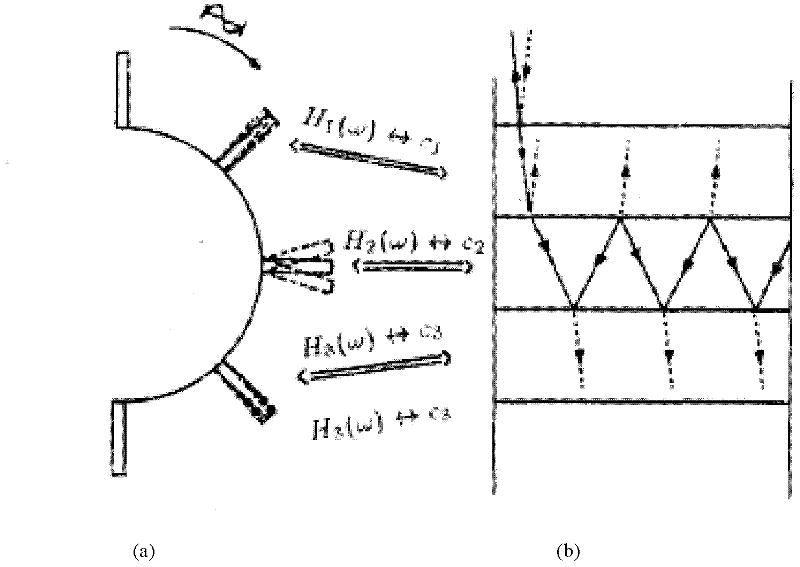
[0095] Excitation source: the frequency of the excitation force caused by the imported reflux The frequency of the exciting force caused by the blades at the exit of the impeller

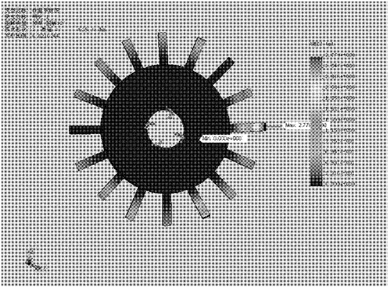
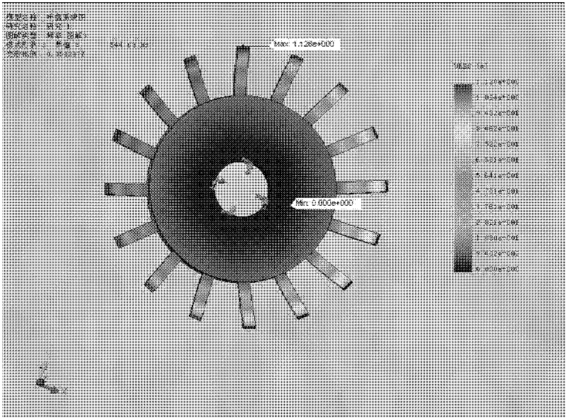
[0096] Finite element model of the impeller: 10-node tetrahedral solid elements...


PUM


Abstract

The invention relates to a centrifugal impeller optimal design method for preventing vibration localization from happening. The method comprises the following steps of: 1, carrying out static strength verification; 2, drawing a vibration mode graph of a plurality of orders of modals in front of an impeller; 3, analyzing a forbidden band and a passband of the impeller; 4, determining the excitation frequency of an excitation source; 5, judging whether the excitation source drops in the forbidden band or is close to the forbidden band; and 6, optimizing the impeller structure and increasing the isolation margin of the forbidden band of the impeller so as to eliminate influence of detuning. According to the centrifugal impeller optimal design method disclosed by the invention, the vibration localization problem of the impeller in the operation process can be effectively solved, the injuries caused by vibration localization and the failure occurrence rate of the impeller in the operation process are reduced, and a centrifugal impeller unit can be ensured to operate safely and reliably for a long time.

Description

technical field [0001] The invention relates to the field of impeller machinery vibration analysis and impeller machinery optimization design, in particular to a centrifugal impeller optimization design method for avoiding vibration localization. Background technique [0002] As an important equipment in metallurgy, building materials, electric power, petroleum, chemical industry, environmental engineering and other industrial sectors, centrifugal compressors are widely used and play a pivotal role in many fields of national economy. For a long time, the vibration problem of large and high-speed centrifugal impellers has always affected the safe and reliable operation of the fan. Once a problem occurs during operation, the production will be interrupted at least, causing economic losses; at worst, it will cause equipment scrapping or even casualties. In recent years, with the rapid development of the national economy and the continuous improvement of unit performance, centri...

Claims


Application Information

Patent Timeline
Patent Type & Authority Applications(China)
IPC IPC(8): F04D29/22F04D29/66
Inventor 张家忠李凯伦康伟雷鹏飞
Owner XI AN JIAOTONG UNIV
Why Eureka
Try Eureka