Rotor Support Mechanism of Rolling Bearing Turbocharger

A technology for turbochargers and rolling bearings, applied to rolling contact bearings, rigid supports for bearing components, bearings for rotational motion, etc., can solve problems such as poor sensitivity of floating bearings, improve reliability, solve lubrication problems, and improve support The effect of stiffness

Inactive Publication Date: 2011-12-14
CHANGZHOU E&E TURBO POWER
View PDF8 Cites 10 Cited by
  • Summary
  • Abstract
  • Description
  • Claims
  • Application Information

AI Technical Summary

Problems solved by technology

[0005] The object of the present invention is to propose a rotor support mechanism for a rolling bearing turbocharger, aiming at the disadvantage of poor sensitivity of the floating bearing that exists in the floating bearing used in the rotor support system of the turbocharger in the above technology. Floating bearings are changed to rolling bearings, and thrust bearings are no longer needed, and thrust bearings are no longer used, which reduces the number of parts, saves costs, and improves system reliability.

Method used


Image

  • Rotor Support Mechanism of Rolling Bearing Turbocharger
  • Rotor Support Mechanism of Rolling Bearing Turbocharger
  • Rotor Support Mechanism of Rolling Bearing Turbocharger

Examples


Embodiment Construction

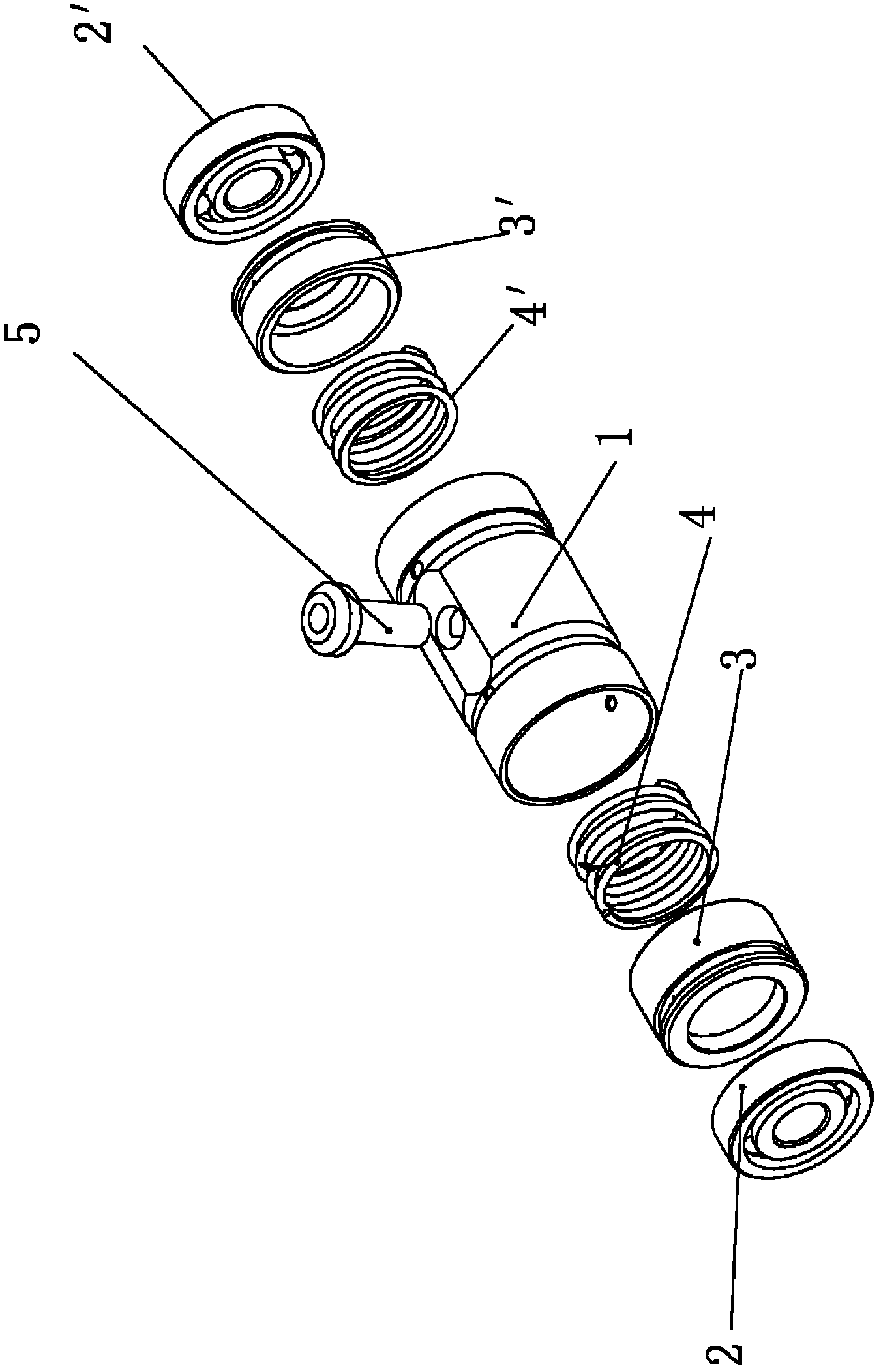
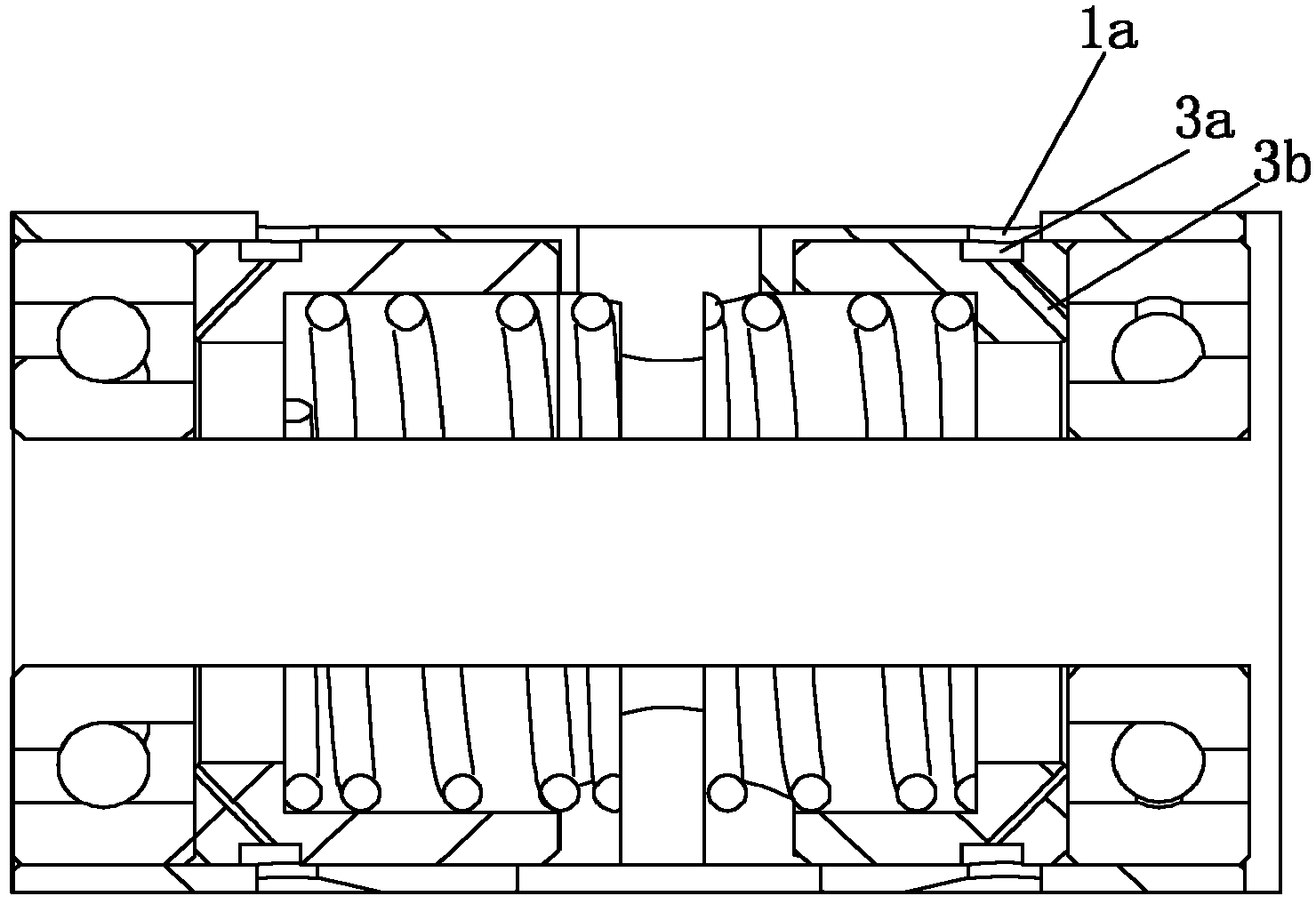
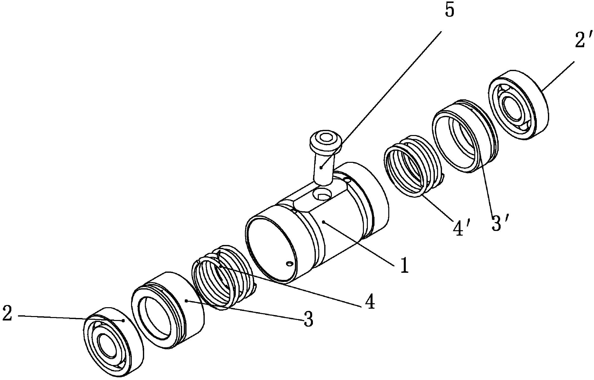
[0017] Such as figure 1 , figure 2 As shown, the rotor supporting mechanism of the rolling bearing turbocharger includes a bearing sleeve and two springs, two thrust sleeves and two bearings arranged in the bearing sleeve 1, and the two springs are respectively spring 4 and spring 4′ , the two thrust sleeves are respectively thrust sleeve 3 and thrust sleeve 3', the two bearings are angular contact rolling bearing 2 and rolling bearing 2', the spring 4 and spring 4' are symmetrically arranged in the bearing sleeve 1 and connected to each other, the two The two thrust sleeves respectively insert the springs into the thrust sleeve 1 from the ends of the two springs and apply pretightening force. The thrust sleeve 3 is arranged on the left side of the spring 4, and the spring 4 is inserted into the thrust sleeve 3, and the thrust sleeve 3 is inserted into the thrust sleeve 3. The sleeve 3' is set on the right side of the spring 4', the spring 4' is inserted into the thrust slee...


PUM


Abstract

The invention belongs to the field of turbochargers for internal combustion engines, in particular to a rotor supporting mechanism of a rolling bearing turbocharger. It includes a bearing sleeve and two springs, two thrust sleeves and two bearings in the bearing sleeve. The two springs are symmetrically arranged in the bearing sleeve and connected to each other. Put the spring into the thrust sleeve and apply pre-tightening force. Two bearings are respectively arranged on the end face of the thrust sleeve. Both bearings are angular contact rolling bearings. The advantage of the present invention is that ceramic rolling bearings are used instead of ordinary floating bearings, which improves the mechanical efficiency and transient response capability of the turbocharger, solves the vibration problem of the rolling bearing turbocharger, and improves the steady-state performance and performance of the turbocharger. The service life of the rolling bearing is improved, the support rigidity of the rolling bearing is improved, the limit speed of the rolling bearing is increased, the requirement of high-speed operation of the turbocharger is met, the lubrication problem of the turbocharger is solved, the reliability of the rolling bearing supercharger is improved, and the balanced transmission The force system meets the requirements for the normal operation of the rolling bearing turbocharger.

Description

technical field [0001] The invention belongs to the field of turbochargers for internal combustion engines, in particular to a rotor supporting mechanism of a rolling bearing turbocharger. Background technique [0002] As is well known, a turbocharger is a device for supplying air to the intake port of an internal combustion engine at a pressure above atmospheric pressure (boost). A conventional turbocharger includes an exhaust gas-driven turbine wheel mounted on a rotating shaft within a turbine housing engaged downstream of the engine outlet manifold. The rotation of the turbine impeller drives the compressor impeller in the pressure casing at the other end to rotate. The compressor wheel delivers compressed air to the engine intake manifold. The rotor of the turbocharger is supported by a bearing system in the housing. [0003] A turbocharger is actually a special kind of air compressor. It uses the high-temperature, high-pressure exhaust gas discharged from the engin...

Claims


Application Information

Patent Timeline
Patent Type & Authority Applications(China)
IPC IPC(8): F01D25/16F16C35/067F16N1/00F02B37/00F02C6/12
CPCY02T10/144F16C25/083F16C19/548F16C35/077F16C2360/24
Inventor 唐云冰章璟璇
Owner CHANGZHOU E&E TURBO POWER
Why Eureka
Try Eureka