Specific direct current motor driving circuit

A DC motor and drive circuit technology, applied in the direction of electric components, electronic commutation motor control, single motor speed/torque control, etc., can solve the problem of reliability, high cost and complicated circuit design affecting the brushless Hall DC motor driver and other problems, to achieve the effect of simple and stable startup, improved reliability, and simplified circuit design

Pending Publication Date: 2022-04-12
陈泽进
View PDF1 Cites 0 Cited by
  • Summary
  • Abstract
  • Description
  • Claims
  • Application Information

AI Technical Summary

Problems solved by technology

[0002] The existing brushless Hall DC motor driver often needs to set up a more complex comparator back electromotive force detection circuit externally, the cost is relatively high, and the circuit design is complicated, which affects the reliability of the brushless Hall DC motor driver

Method used


Image

  • Specific direct current motor driving circuit
  • Specific direct current motor driving circuit
  • Specific direct current motor driving circuit

Examples


Embodiment Construction

[0012] In order to understand the above-mentioned purpose, features and advantages of the present invention more clearly, the present invention will be further described in detail below in conjunction with the accompanying drawings and specific embodiments.

[0013] It should be noted that, in the case of no conflict, the embodiments of the present invention, that is, the features in the embodiments may be combined with each other.

[0014] In the following description, many specific details are set forth in order to fully understand the present invention. However, the present invention can also be implemented in other ways different from those described here. Therefore, the protection scope of the present invention is not limited by the specific details disclosed below. EXAMPLE LIMITATIONS.

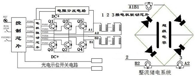
[0015] The present invention includes a switch circuit group, a motor drive chip, a photoelectric position display switch circuit, a resistor voltage divider network and a rectification ...


PUM


Abstract

A specific direct current motor driving circuit is characterized by comprising a switch circuit group, a motor driving chip, a photoelectric position indicating switch circuit, a resistance voltage dividing network and a rectification electricity storage system. The control circuit is essentially characterized in that two single-phase motors nested with each other rotate reversely, an outer motor controls on-off and reversing of current when crossing a zero point, an inner motor pushes the outer motor to cross the zero point through meshing of a three-star wheel, and the outer motor pushes the inner motor to cross the zero point through meshing of the three-star wheel until the inner motor reaches the zero point. The beneficial effects of the invention are that the device obtains the induced reverse electromotive force through the resistor voltage dividing network, cooperates with the switching-on and switching-off signals of the photoelectric position indicating switch circuit, precisely and stably displays the position of the zero crossing point, and transmits the position of the zero crossing point to a motor driving chip; a controllable electronic switch is controlled to alternately conduct motor inner and outer windings and a motor driving power supply at equal phase intervals according to a specific sequence, starting is easy and stable, and therefore the motor is driven to rotate. The circuit design is simplified, the reliability is improved, and the cost is saved.

Description

technical field [0001] The present invention relates to the technical field of motor control, in particular to a specific DC motor drive circuit. Background technique [0002] Existing brushless Hall DC motor drivers often require a relatively complex comparator back electromotive force detection circuit externally. The cost is relatively high and the circuit design is complicated, which affects the reliability of the brushless Hall DC motor driver. Contents of the invention [0003] The present invention proposes a specific DC motor drive circuit based on another authorized patent of the inventor of this case, "Double Rotor Planetary Wheel Energy Storage Booster" (patent number: ZL 202021419841.3). [0004] "Double Rotor Planetary Gear Energy Storage Booster Device" (Patent No.: ZL 202021419841.3) innovatively changes the three-phase alternating drive into an alternate drive with dislocation of inner and outer stator windings. The most prominent effect is: the planetary g...

Claims


Application Information

Patent Timeline
Patent Type & Authority Applications(China)
IPC IPC(8): H02K16/02H02K1/27H02K7/116H02P6/08H02P6/182
Inventor 陈泽进陈天恩
Owner 陈泽进
Why Eureka
Try Eureka