Eureka AIR delivers breakthrough ideas for toughest innovation challenges, trusted by R&D personnel around the world.

Switching tube junction temperature detection method, motor controller, motor control system and medium

A technology of motor control and detection method, applied in the field of motor control system and computer-readable storage medium, can solve the problems affecting the temperature protection of switching devices, inaccurate temperature detection of switching devices, and limited sensing ability of internal temperature changes of switching devices, etc. high accuracy effect

Pending Publication Date: 2022-04-12
GUANGDONG WELLING ELECTRIC MACHINE MFG
View PDF0 Cites 0 Cited by
  • Summary
  • Abstract
  • Description
  • Claims
  • Application Information

AI Technical Summary

Problems solved by technology

Among them, the conventional temperature protection method for discrete switching devices is usually to use a temperature resistance around the switching device for temperature protection. Although this method provides temperature sensing capability, because the temperature resistance receives the spatial radiation temperature of the switching device, Affected by the installation position of the temperature resistor, this method has limited ability to sense the internal temperature change of the switching device, resulting in inaccurate temperature detection of the switching device, which in turn affects the temperature protection of the switching device

Method used


Image

  • Switching tube junction temperature detection method, motor controller, motor control system and medium
  • Switching tube junction temperature detection method, motor controller, motor control system and medium
  • Switching tube junction temperature detection method, motor controller, motor control system and medium

Examples


Embodiment Construction

[0028] Embodiments of the present invention are described in detail below, examples of which are shown in the drawings, wherein the same or similar reference numerals designate the same or similar elements or elements having the same or similar functions throughout. The embodiments described below by referring to the figures are exemplary and are intended to explain the present invention and should not be construed as limiting the present invention.

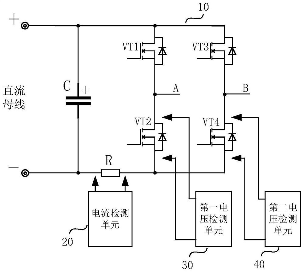
[0029] In an embodiment of the present invention, the motor control system may include: an H bridge connected to a DC bus for driving the motor to work.

[0030] Specifically, refer to figure 1As shown, the H bridge includes an A-phase bridge arm and a B-phase bridge arm, the A-phase bridge arm includes an upper tube VT1 and a lower tube VT2, and the B-phase bridge arm includes an upper tube VT3 and a lower tube VT4, wherein the first of the upper tube VT1 The first end of the lower tube VT2 is connected to the second end of the...


PUM


Abstract

The invention discloses a switching tube junction temperature detection method, a motor controller, a motor control system and a medium. The method comprises the following steps: acquiring direct current bus current; determining a motor phase current when a lower tube of any phase of bridge arm in the H bridge is conducted according to the DC bus current, and obtaining a tube voltage drop when the lower tube of any phase of bridge arm in the H bridge is conducted; determining the conduction current when the lower tube of at least one phase of bridge arm in the H bridge is conducted according to the motor phase current when the lower tube of any phase of bridge arm in the H bridge is conducted, and determining the conduction resistance when the lower tube of the at least one phase of bridge arm is conducted according to the conduction current when the lower tube of the at least one phase of bridge arm is conducted and the tube voltage drop when the lower tube of the at least one phase of bridge arm is conducted; and determining the junction temperature of the lower tube of the at least one phase of bridge arm according to the conduction resistance when the lower tube of the at least one phase of bridge arm is conducted. According to the method, the on-resistance is calculated according to the tube voltage drop and the on-current, and the junction temperature of the lower tube is determined based on the on-resistance, so that the obtained junction temperature of the lower tube has relatively high accuracy.

Description

technical field [0001] The invention relates to the technical field of motor control, in particular to a method for detecting junction temperature of a switch tube in a motor control system, a motor controller, a computer-readable storage medium and a motor control system. Background technique [0002] In the field of home appliance motor control or small light electric vehicle control, based on cost and space considerations, motor controllers mostly use single-resistor current sampling to control the motor, and large-scale switching devices are implemented using discrete devices. Among them, the conventional temperature protection method for discrete switching devices is usually to use a temperature resistance around the switching device for temperature protection. Although this method provides temperature sensing capability, because the temperature resistance receives the spatial radiation temperature of the switching device, Affected by the installation position of the te...

Claims


Application Information

Patent Timeline
Patent Type & Authority Applications(China)
IPC IPC(8): H02P7/03H02M1/088
Inventor 宾宏张凯赵小安陈帅
Owner GUANGDONG WELLING ELECTRIC MACHINE MFG
Why Eureka
Eureka Blog
Learn More