Power supply time sequence control circuit
A timing control circuit and circuit technology, which is applied in the direction of electrical components, electronic switches, pulse technology, etc., can solve problems such as damage to the power chip of the subsequent stage, high power quality requirements, and failure to output power enable signals.
- Summary
- Abstract
- Description
- Claims
- Application Information
AI Technical Summary
Problems solved by technology
Method used
Image

Examples
Embodiment 1
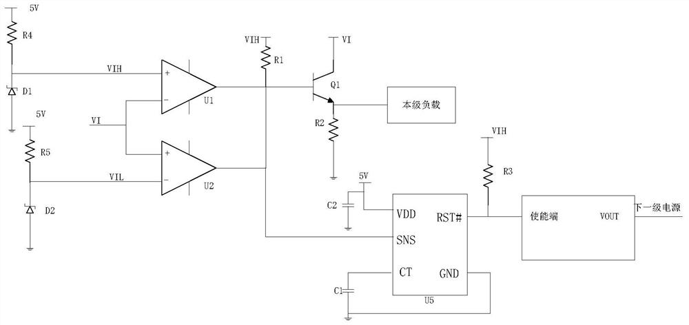
[0036] like image 3 As shown, it is a specific circuit of this specific embodiment, and the window detector includes comparators U1 and U2. Both U1 and U2 have four pins: non-inverting input, inverting input, positive power supply pin, and negative power supply pin. The non-inverting input of U1 is connected to VIH, VIH is the maximum value of the normal voltage of VI, the inverting input of U1 is connected to VI and the non-inverting input of U2, the inverting input of U2 is connected to VIL, and VIL is the normal voltage of VI The minimum value of U1, the output of U1 is pulled up to VIH through R1.
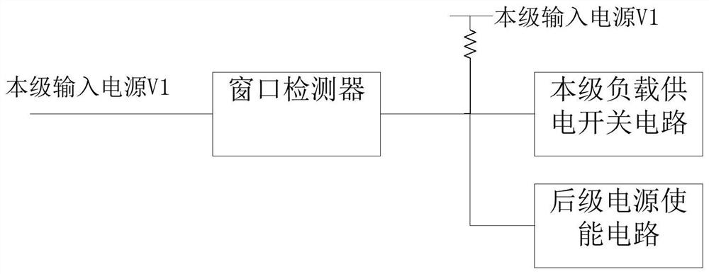
[0037] The post-stage power enable circuit is U3, the enable end of U3 is connected with the output of the window detector, and the output end of U3 is connected with the input of the post-stage power supply.
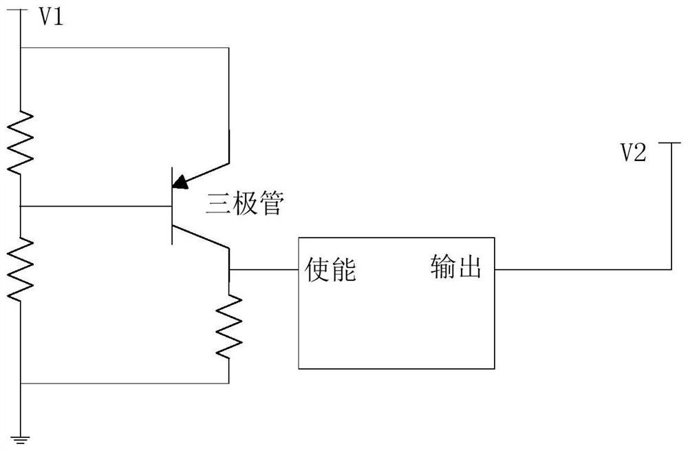
[0038] The load power supply switching circuit of this stage includes transistors Q1 and R2. The base of Q1 is connected to the output of the window detector and the...
Embodiment 2
[0042] attached Figure 4It is an extension of Embodiment 1. The optocoupler is used instead of the op amp as the window detector. Since the input impedance of the op amp is nearly infinite, the current flowing into the op amp is very small, and only needs voltage. Between the back-end circuits will be turned on. Even though VI is only the coupled voltage, not the real voltage output by the pre-stage power supply. If optocoupler is used, the VI must meet the two conditions of voltage and current, coupling interference voltage, no current drive capability, and window detector does not work, so as to avoid wrongly turning on the lower voltage due to wrongly coupled voltage.
[0043] When the window detector detects that the voltage is between the maximum value VIH and VIL, the open-drain output is pulled up to VIH by the external pull-up resistor R1, and VIH>the threshold of the voltage monitoring chip U5, and the CT terminal capacitor C1 is fully charged, the output The termi...
PUM
 Abstract
Description
Claims
Application Information
 - R&D
- Intellectual Property
- Life Sciences
- Materials
- Tech Scout
- Unparalleled Data Quality
- Higher Quality Content
- 60% Fewer Hallucinations
Browse by: Latest US Patents, China's latest patents, Technical Efficacy Thesaurus, Application Domain, Technology Topic, Popular Technical Reports.
© 2025 PatSnap. All rights reserved.Legal|Privacy policy|Modern Slavery Act Transparency Statement|Sitemap|About US| Contact US: help@patsnap.com