Metal processing protection mechanism

A protection mechanism and metal processing technology, which is applied in the direction of metal processing machinery parts, metal processing equipment, manufacturing tools, etc., can solve problems such as potential safety hazards, vibration of operating parts, etc., and achieve the effect of improving safety

Pending Publication Date: 2022-04-15
哈工大泰州创新科技研究院有限公司
View PDF0 Cites 0 Cited by
  • Summary
  • Abstract
  • Description
  • Claims
  • Application Information

AI Technical Summary

Problems solved by technology

[0002] In metal processing operations, operating parts often vibrate due to poor maintenance or aging of equipment, and there are certain potential safety hazards

Method used


Image

  • Metal processing protection mechanism
  • Metal processing protection mechanism
  • Metal processing protection mechanism

Examples


Embodiment 1

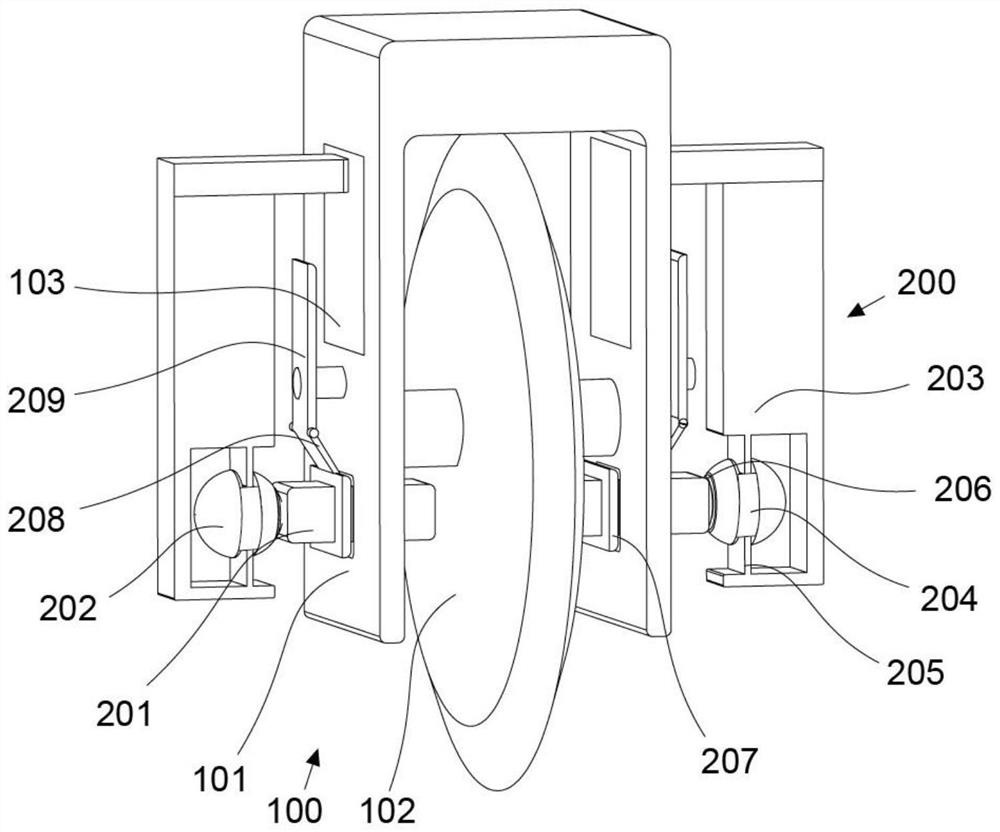
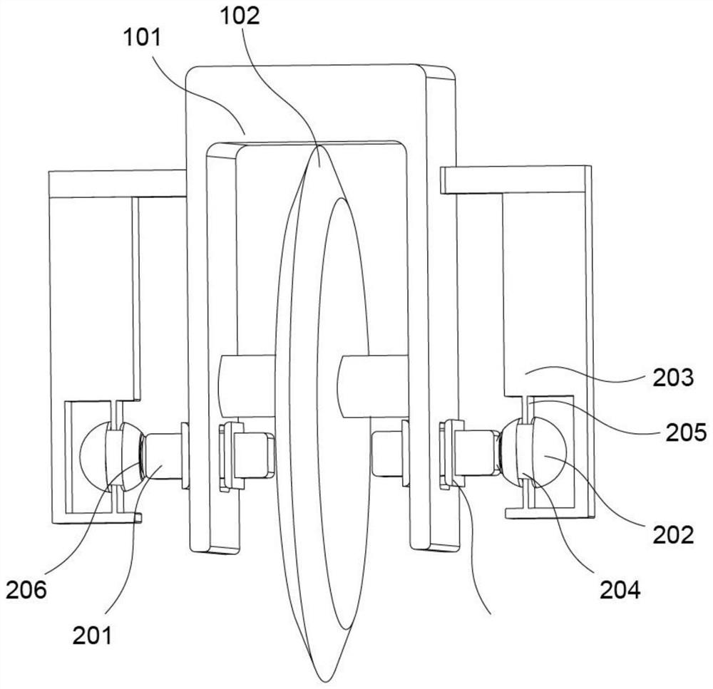
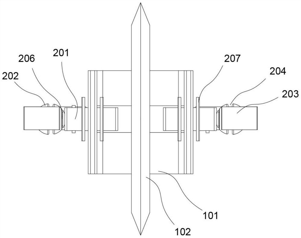
[0025] refer to Figure 1-3 , provides a schematic diagram of the overall structure of a metal processing protection mechanism, a metal processing protection mechanism includes a frame assembly 100, including a main frame 101 and a processing disc 102 arranged on the main frame 101; and, a protection assembly 200, including a set The trigger bar 201 on both sides of the main frame 101 , the limit ball 202 arranged at one end of the trigger bar 201 , and the protection plate 203 matched with the limit ball 202 .

[0026] Specifically, a metal processing protection mechanism includes a frame assembly 100, including a main frame 101 and a processing disc 102 arranged on the main frame 101, the main frame 101 is a U-shaped frame, and the processing disc 102 is placed in it; and, the protection The assembly 200 includes trigger bars 201 arranged on both sides of the main frame 101, and a limit ball 202 arranged at one end of the trigger bar 201. The trigger bars 201 are arranged cl...

Embodiment 2

[0029] refer to Figure 1-3 , this embodiment is different from the first embodiment in that: the limit ball 202 is provided with a card slot 204, and the protective plate 203 is provided with a limit elastic piece 205 that cooperates with the card slot 204, and the limit elastic piece 205 is placed in the card slot 204; the end of the limit ball 202 away from the protective plate 203 is provided with a chute 206 that cooperates with the limit shrapnel 205; the two sides of the main frame 101 are provided with openings, and the trigger bar 201 is placed in the opening, and the trigger bar 201 is provided with Clamping plates 207 located on both sides of the opening; the diameter of the clamping plate 207 is larger than the size of the opening, the material of the clamping plate 207 is rubber, and the other structures are the same as in Embodiment 1.

[0030] Specifically, the limit ball 202 is provided with a card slot 204, and the protective plate 203 is provided with a limit...

Embodiment 3

[0035] refer to Figure 1-3 What this embodiment is different from the above embodiments is: the top of the clamping plate 207 is fixedly connected with a push plate 208, the top of the push plate 208 is movably connected with a movable plate 209, and the movable plate 209 is rotatably connected with the main frame 101; the main frame 101 is provided with The stabilizing plate 103 that cooperates with the movable plate 209, the stabilizing plate 103 is movably connected with the main frame 101; the bottom of the protective plate 203 is provided with a cavity, and the limit ball 202 is placed therein, and the limit ball 202 is not in contact with the inner wall of the cavity. The position elastic pieces 205 are fixedly arranged on the top and bottom of the cavity; the trigger bar 201 is located on both sides of the processing disk 102, and the rest of the structure is the same as that of the second embodiment.

[0036]Specifically, the top of clamping plate 207 is fixedly conne...


PUM


Abstract

The invention discloses a metal processing protection mechanism which comprises a frame body assembly, a plurality of clamping assemblies, a plurality of clamping assemblies and a plurality of clamping assemblies, wherein the frame body assembly comprises a main frame and a processing disc arranged on the main frame; the protection assembly comprises trigger strips arranged on the two sides of the main frame, limiting balls arranged at one ends of the trigger strips, and protection plates matched with the limiting balls. A clamping groove is formed in the limiting ball, a limiting elastic piece matched with the clamping groove is arranged on the protection plate, and the limiting elastic piece is placed in the clamping groove. The end, away from the protection plate, of each limiting ball is provided with a sliding groove matched with the corresponding limiting elastic piece, and all the parts are in linkage to protect and stabilize the machining disc. And the protection assembly can be started to protect and stabilize the machining disc so as to prevent the machining disc from breaking and breaking to damage metal and human bodies, and the safety of the device is improved.

Description

technical field [0001] The invention relates to the technical field of protection mechanisms, in particular to a metal processing protection mechanism. Background technique [0002] In metal processing operations, operating parts often vibrate due to poor equipment maintenance or aging, which poses certain safety hazards. Contents of the invention [0003] The purpose of this section is to outline some aspects of embodiments of the invention and briefly describe some preferred embodiments. Some simplifications or omissions may be made in this section, as well as in the abstract and titles of this application, to avoid obscuring the purpose of this section, the abstract and titles, and such simplifications or omissions should not be used to limit the scope of the invention. [0004] The present invention has been developed in view of the above-described problems in existing metalworking operations. [0005] It is therefore an object of the present invention to provide a m...

Claims


Application Information

Patent Timeline
Patent Type & Authority Applications(China)
IPC IPC(8): B23D19/00B23D33/00B23Q11/08
Inventor 孟惠平
Owner 哈工大泰州创新科技研究院有限公司
Why Eureka
Try Eureka