Impressing device on soap production line

A production line and soap technology, applied in the direction of cooling soap, embossing/polishing soap, etc., can solve problems such as low work efficiency, affecting the quality of finished soap products, and inability to replace molds

Inactive Publication Date: 2022-04-15
德清净波日化有限公司
View PDF0 Cites 0 Cited by
  • Summary
  • Abstract
  • Description
  • Claims
  • Application Information

AI Technical Summary

Problems solved by technology

[0005] The invention provides an embossing device on a soap production line, one purpose of which is to have the characteristics of limiting and controlling the position of soap, so as to solve the problem that the embossing position of soap is not easy to control, affects the quality of finished soap, and has low work efficiency The problem; another purpose is to solve the problem that the size of the soap is not the same, the required embossing mold is also different, and the traditional device cannot replace the mold, so as to achieve the replacement of the embossing mold for different sizes of soap Effect

Method used


Image

  • Impressing device on soap production line
  • Impressing device on soap production line
  • Impressing device on soap production line

Examples


Embodiment 1

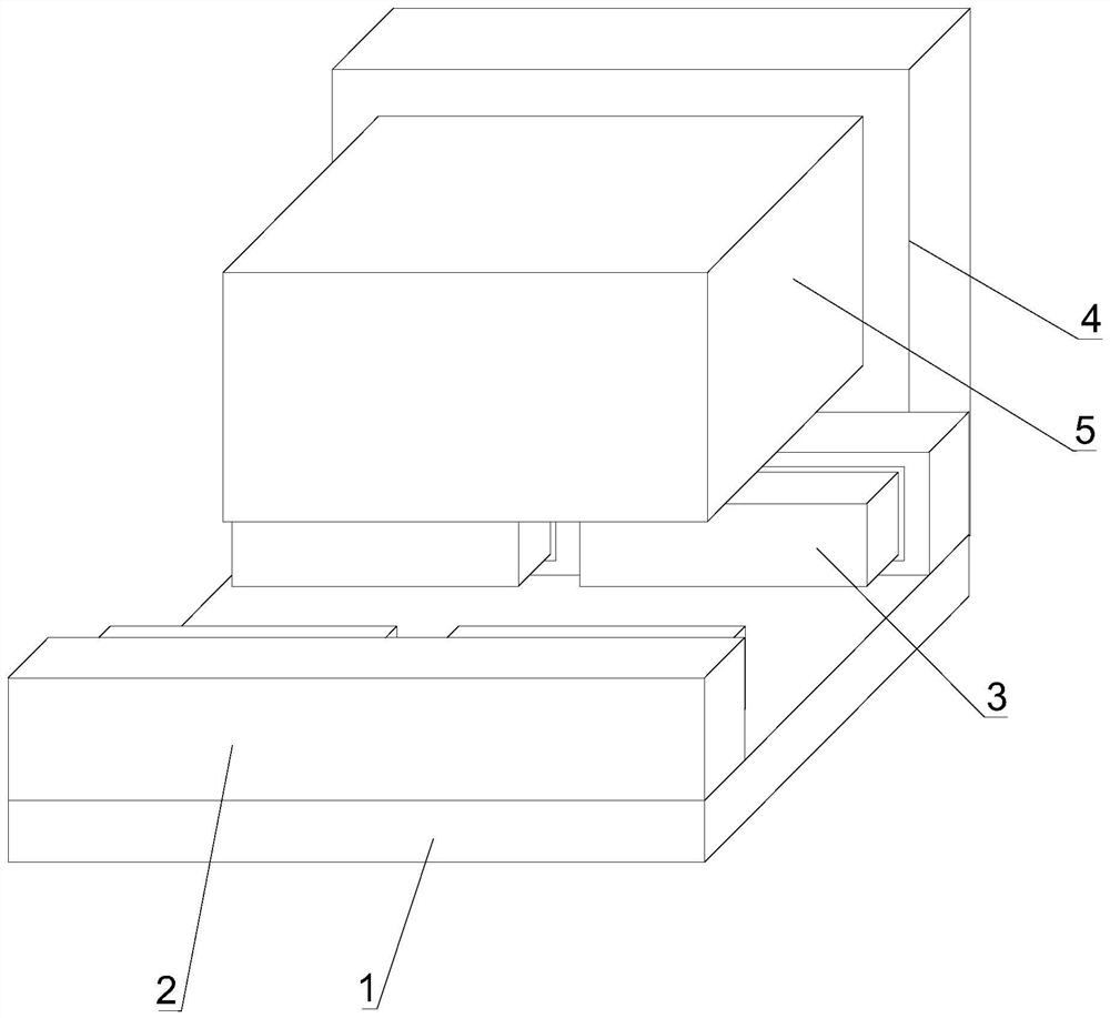
[0036] Such as Figure 1-6 Shown, the present invention provides a kind of embossing device on the soap production line, comprises soap production embossing device 1, lateral top plate 2, soap stop device 3, back side working plate 4 and soap embossing device shell 5, soap The side top plate 2 is detachably installed on the front and rear sides of the top of the production embossing device 1, and the soap limiter 3 is detachably installed on one side of the lateral top plate 2. The back side of the soap production embossing device 1 The backside working plate 4 is detachably installed on the top, and the soap embossing device shell 5 is detachably installed on the front outer surface of the backside working plate 4 .

[0037] In this embodiment, the cut soap is transported by the soap production embossing device 1, and the soap is limited in position by the soap limiting device 3, and then passed through the soap embossing device shell on the surface of the back side working p...

Embodiment 2

[0040] Such as Figure 1-6 As shown, on the basis of Example 1, the present invention provides a technical solution: preferably, a propeller 31 is arranged inside the left side of the soap limiting device 3, and the output end of the propeller 31 extends to the soap limiting device 3 On the outer surface of the right side of the soap limiter 3, a lap block 32 is fixedly connected on the outer surface of the right side of the soap limiting device 3, and an expansion plate 33 is detachably connected to the output end of the propeller 31, and the right side of the expansion plate 33 is on the upper side. An elastic shaft is arranged on the outer surface, and an opening and closing plate 34 is arranged on the outer surface of the elastic shaft, and an empty groove is arranged on the right outer surface of the unfolding plate 33, and a buffer wire is detachably connected to the inner surface of one side of the empty groove. 35. One end of the buffer wire one 35 is detachably connec...

Embodiment 3

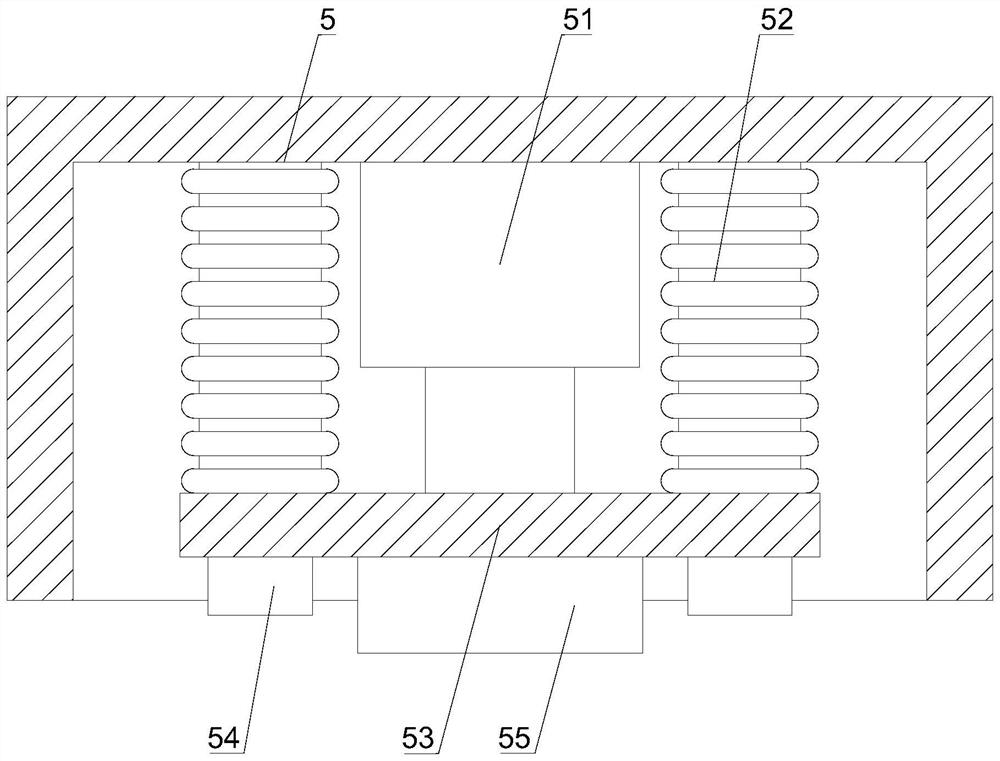
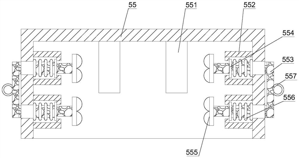
[0043] Such as Figure 1-6 As shown, on the basis of Embodiment 1, the present invention provides a technical solution: preferably, the soap embossing device shell 5 includes a mold casing 55, and the top inner surface of the mold casing 55 is detachably installed with a snap-fit Limiting conductive rods 551, side vertical plates 552 are detachably installed on the inner surfaces of both sides of the mold casing 55, and C-shaped pull plates 553 are movably socketed on the outer surfaces of both sides of the mold casing 55, C-shaped One end of the pulling plate 553 extends to the inner surface of the mold casing 55, and the limit clamping plate 554 is arranged on the outer surface of the inner side vertical plate 552, and one end of the C-shaped pulling plate 553 is detachably connected with a soft extrusion. Pressing head 555, buffer pushing wire 556 is movably sleeved on the outer surface of inner side C-shaped pulling plate 553, and one side outer surface of limit clamping p...


PUM


Abstract

The invention discloses an impressing device on a soap production line, and relates to the technical field of soap impressing, the impressing device comprises a soap production impressing device, lateral top plates, a soap limiting device, a back side working plate and a soap impressing device shell, the lateral top plates are detachably mounted on the front and back side surfaces of the top of the soap production impressing device; and a soap limiting device is detachably mounted on the outer surface of one side of the lateral top plate. The bottom plate is pushed through the pusher, length shrinkage is conducted in cooperation with the telescopic hose, then high-temperature shape and pattern coining is conducted on the surface of soap through the mold sleeve shell, after coining is completed, cold air circulation is conducted on the interior of an exhaust cooling opening in cooperation with the telescopic hose, and the soap subjected to high-temperature coining is rapidly cooled; the soap high-temperature coining and cooling device has the advantages of conducting high-temperature coining and cooling on the soap, solves the problem that cracks appear on the surface of the soap due to traditional hard pressing, and achieves the effects of conducting high-temperature coining and cooling on the soap.

Description

technical field [0001] The invention relates to the technical field of soap embossing, in particular to an embossing device on a soap production line. Background technique [0002] The finished soap is made by extruding the raw materials through an extruder to make it into a long strip, and then cutting, embossing and packaging. However, when the cut soap is embossed one by one, the soap embossing position is not easy Control, poor processing quality, affect the quality of soap finished products, and lower work efficiency. There are following problems at prior art: [0003] 1. Cutting the processed soap. When the cut soap is embossed one by one, the soap embossing position is not easy to control, which affects the quality of the finished soap, and the work efficiency is low; [0004] 2. The size and shape of different soaps are different, and the stamping molds required for stamping are also different. Traditional devices cannot replace the molds. Contents of the inventi...

Claims


Application Information

Patent Timeline
Patent Type & Authority Applications(China)
IPC IPC(8): C11D13/28C11D13/12
CPCC11D13/28C11D13/12
Inventor 徐光辉
Owner 德清净波日化有限公司
Why Eureka
Try Eureka