Intelligent transmission method and system for electric fan

A transmission system and fan technology, applied in the transmission of mechanical power, control of wind turbines, monitoring of wind turbines, etc., can solve problems such as only paying attention to, but not considering the rotation device of the machine head, and achieve the effect of precise maintenance

Active Publication Date: 2022-04-15
HANGZHOU JIE DRIVE TECH
View PDF8 Cites 0 Cited by
  • Summary
  • Abstract
  • Description
  • Claims
  • Application Information

AI Technical Summary

Problems solved by technology

Chinese invention patent CN202011635545.1 discloses a remote intelligent monitoring system for wind turbine transmission chains, including: a data acquisition module for real-time collection of monitoring signals of wind turbine components; Frequency domain feature calculation to obtain feature data; analysis and diagnosis module, used to analyze and diagnose feature data according to preset alarm thresholds, obtain diagnostic information, and generate alarm information according to the diagnostic information; communication module, used to realize communication with remote management module data interaction; the remote management module is used to store and display the transmission data of the data processing module and the analysis and diagnosis module. Maintenance personnel provide accurate and reliable decision-making data basis, which can detect wind turbine component failures in time, avoid secondary hazards, and cause greater losses. This application focuses on handling the fault status of the wind turbine head transmission system, without considering the wind turbine head rotation device, and Only focus on the diagnosis of faults, without intelligent control of the normal operation and maintenance of the fan

Method used


Image

  • Intelligent transmission method and system for electric fan
  • Intelligent transmission method and system for electric fan
  • Intelligent transmission method and system for electric fan

Examples


Embodiment Construction

[0027] Exemplary embodiments of the present disclosure will be described in more detail below with reference to the accompanying drawings. Although exemplary embodiments of the present disclosure are shown in the drawings, it should be understood that the present disclosure may be embodied in various forms and should not be limited by the embodiments set forth herein. Rather, these embodiments are provided for more thorough understanding of the present disclosure and to fully convey the scope of the present disclosure to those skilled in the art.

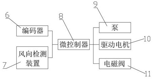
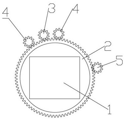
[0028] see figure 1 and figure 2, an intelligent transmission system for electric fans, including a machine head fixing seat 1 and a ring gear seat base 2, and also includes a wind direction detection device 7 for detecting wind direction, the machine head fixing seat 1 is used to install the fan head, and the machine head is fixed The seat 1 is fixedly installed on the ring gear base 2, and the ring gear base 2 is provided with ...


PUM


Abstract

An intelligent transmission system for an electric fan comprises a machine head fixing seat, a gear ring seat base and a wind direction detection device, the gear ring seat base is provided with a rotation driving device, the rotation driving device comprises a driving gear, a driving motor and a microcontroller, the driving gear is matched with a gear of the gear ring seat base, and the driving gear is connected with an output shaft of the driving motor; the two sides of the driving gear are each provided with a first auxiliary gear, the first auxiliary gears are matched with the gear ring seat base gear, meshing triggering oil supply structures are arranged on the first auxiliary gears, and the first auxiliary gears are used for forced lubricating oil supply before the driving gear is meshed with the gear ring seat base; a gear ring base position detection device is arranged, and the position detection device is used for detecting the real-time angle and the rotation angle of the gear ring base; and the wind direction detection device, the driving motor and the position detection device are electrically connected with the microcontroller. Intelligent control is achieved by monitoring and adjusting the position of the fan head in real time and matching with matched maintenance of the driving auxiliary gear.

Description

technical field [0001] The invention relates to the technical field of intelligent transmission, in particular to an intelligent transmission method and system for electric fans. Background technique [0002] Wind power generation refers to the power generation method that uses wind turbines to directly convert wind energy into electrical energy. It is currently the most widely used new energy power generation method. At present, the wind turbine head rotates around the wind turbine tower through the head rotation device. Since the wind turbines are generally installed in relatively remote or high-lying locations, and the head rotation device used to drive the wind turbine head to rotate is even installed on the top of the wind turbine tower, which involves high-altitude operations and is difficult to maintain. Therefore, how to monitor the state of the drive of the electric fan in real time and adjust the speed according to the real-time working conditions is an urgent pro...

Claims


Application Information

Patent Timeline
Patent Type & Authority Applications(China)
IPC IPC(8): F03D7/02F03D15/00F03D17/00F03D80/70
CPCY02E10/72
Inventor 陈德木陆建江
Owner HANGZHOU JIE DRIVE TECH
Why Eureka
Try Eureka