
Air supply adjustment valve for railway freight cars

A technology for railway wagons and regulating valves, which is applied in the direction of railway car body parts, control valves, balance valves, etc., and can solve the problem of reducing the reliability and safety of the air supply regulating valve, and the deformation of the copper diaphragm pressure ring and copper diaphragm , the difficulty of controlling the air filling speed, etc., to achieve the effect of improving the safety of use, reducing the number of connection points, and preventing loosening and reliability

Active Publication Date: 2022-06-24
CRRC TAIYUAN CO LTD
View PDF10 Cites 0 Cited by
  • Summary
  • Abstract
  • Description
  • Claims
  • Application Information

AI Technical Summary

Problems solved by technology

The pressure regulating valve part of the existing air supply regulating valve is a spring box and the valve body that press the copper diaphragm pressure ring and copper diaphragm to form a sealing structure, and the maintenance cost is low. However, with the vibration of the air filling and vehicle operation, the copper diaphragm The sheet pressure ring and the copper diaphragm will be deformed, resulting in leakage of the pressure regulating valve, and the stroke of the copper diaphragm is used to control the air filling speed. There is a problem that the stroke of the copper diaphragm is too small, which will easily lead to the difficulty of controlling the air filling speed, reducing the Operation reliability and safety of air supply adjustment valve

Method used


Image

  • Air supply adjustment valve for railway freight cars
  • Air supply adjustment valve for railway freight cars
  • Air supply adjustment valve for railway freight cars

Examples


Embodiment 1

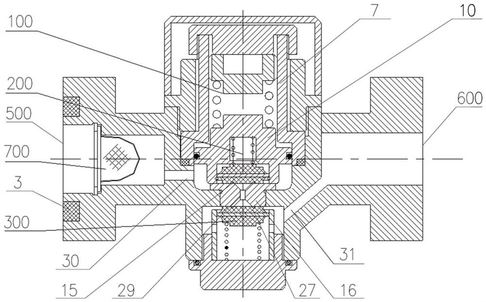
[0097] refer to Figure 1-Figure 10 As shown, this embodiment provides an air supply adjustment valve for a railway freight car, including:

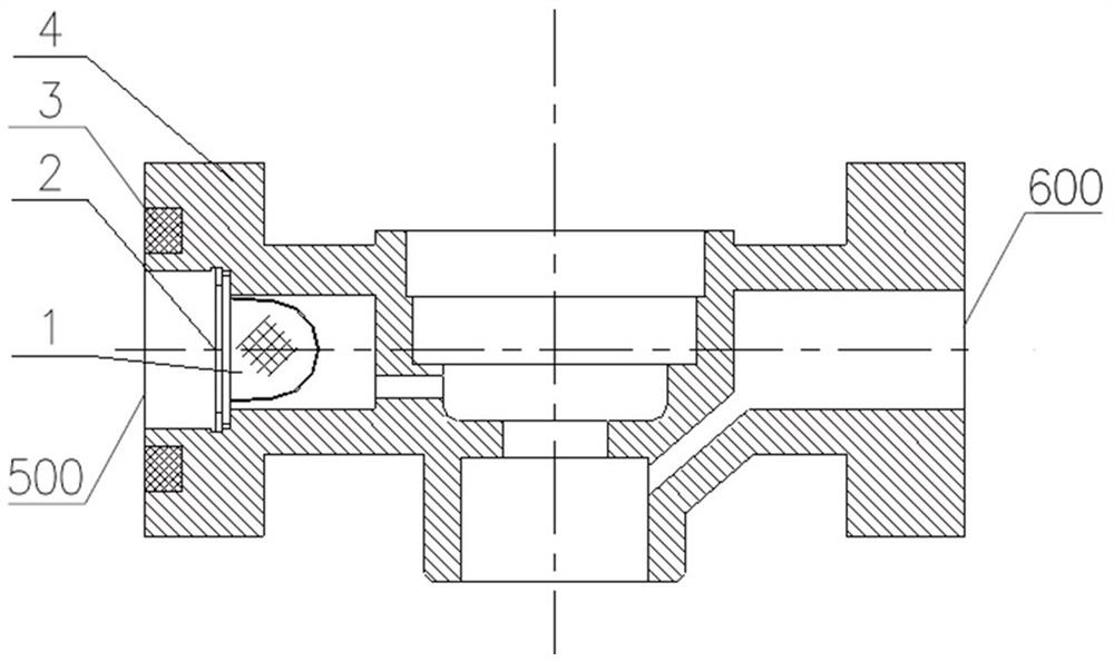
[0098] The valve body 4, the two ends of the valve body 4 are respectively provided with an air inlet hole 500 and an air outlet hole 600, the middle part of the valve body 4 is sequentially provided with an upper cavity and a lower cavity from top to bottom, and a The valve seat 16, the middle part of the valve seat 16 is provided with a first ventilation hole 29 that first shrinks and then gradually expands from top to bottom;

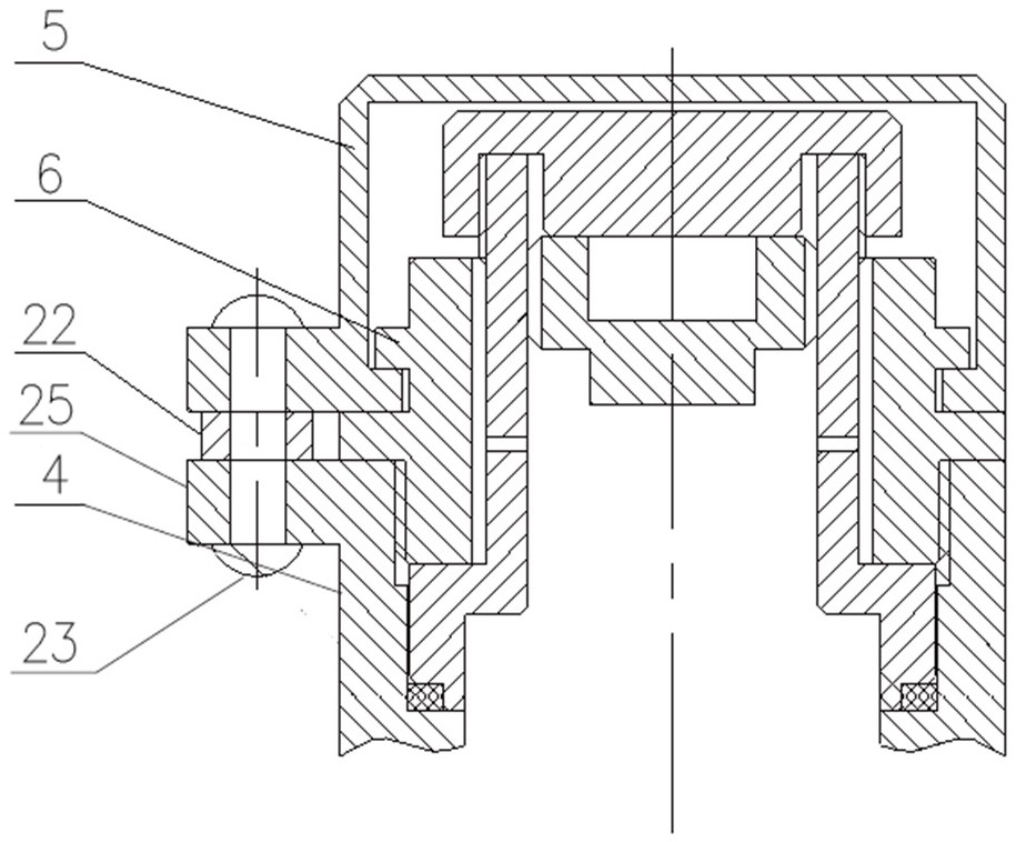
[0099] The air charging valve part 200 is arranged in the upper chamber. The air charging valve part 200 includes a piston 10 and a piston cylinder 7 which are slidably arranged in the upper chamber. The lower part of the piston 10 is provided with a first sandwich valve 15. A first connection hole 30 communicating with the air inlet hole 500 is provided, and the first connection hole 30 is located below the p...


PUM


Abstract

The invention provides an air supply regulating valve for railway freight cars, belonging to the technical field of railway freight cars, comprising: the two ends of the valve body are respectively provided with air inlet holes and air outlet holes, and the middle part of the valve body is provided with upper chambers sequentially from top to bottom and the lower chamber, a valve seat is set between the upper chamber and the lower chamber, and the middle part of the valve seat is provided with a first ventilation hole that first shrinks and then gradually expands from top to bottom; the air filling valve part is arranged in the upper chamber, and the air filling valve part It includes a piston and a piston cylinder that are slidably arranged in the upper chamber, and the lower part of the piston is provided with a first sandwich valve; the check valve part is arranged in the lower chamber, and the check valve part includes a second sandwich valve that is slidably arranged in the lower chamber. The sandwich valve and the first sandwich valve can block the first ventilation hole from the lower side and the upper side, respectively. The passage diameter of the first ventilation hole is used to control the air filling speed of the air supply adjusting valve, which solves the problem that the air filling speed of the original air supply adjusting valve is difficult to control, and improves the operational reliability and safety of the air supply adjusting valve.

Description

technical field [0001] The invention belongs to the technical field of railway freight cars, and more particularly relates to an air supply adjustment valve for railway freight cars. Background technique [0002] Railway hopper cars account for a relatively low proportion of the number of railway transportation equipment, but they have irreplaceable advantages and functions in transporting specific goods. It is mainly divided into coal hopper trucks and ballast hopper trucks. The loading and unloading methods are top loading and unloading. With the increasing cost of labor, users put forward higher demands on the use of hopper trucks, requiring efficient loading and unloading efficiency. , with fewer people and safer operation. Therefore, at present, most hopper trucks have realized the wind-controlled opening and closing of the bottom door, which improves the loading and unloading efficiency of hopper trucks and reduces the labor cost of enterprises. [0003] The air supp...

Claims


Application Information

Patent Timeline
Patent Type & Authority Patents(China)
IPC IPC(8): F16K17/06F16K17/164F16K15/06F16K15/18F16K35/00B61H11/10B60T15/02B01D46/10
Inventor 黄刚强赵明赵祖兴袁太红哈彩霞李旭英魏文超吴佳张蓓刘文胜杨景林闫庆飞梁晓东师甲宁刘文凯王锐杰
Owner CRRC TAIYUAN CO LTD
Learn More