
Detection device for escaping charged particle flow outside cutting area

A technology of charged particles and detection devices, applied in measurement devices, measurement of current/voltage, measurement of electrical variables, etc., can solve problems such as increasing measurement difficulty, affecting measurement accuracy, interfering with current, etc., to reduce the cost of detection equipment, suitable for The effect of wide range and improved measurement accuracy

Pending Publication Date: 2022-04-15
ZHEJIANG UNIV OF TECH
View PDF0 Cites 0 Cited by
  • Summary
  • Abstract
  • Description
  • Claims
  • Application Information

AI Technical Summary

Problems solved by technology

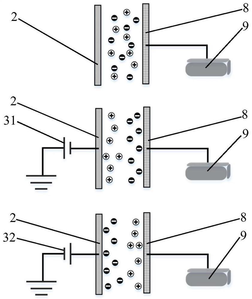
This method of applying bias voltage can distinguish the polarity of charged particle flow, but its disadvantages are also prominent, mainly because the collection plate loaded with bias voltage can form a divergent electric field in space to attract charged particles with opposite polarities , theoretically can change the current size of the active test loop
However, because the current formed by charged particles is extremely small, the bias voltage source will interfere with the current formed by charged particles, which will affect the measurement accuracy and increase the difficulty of measurement

Method used


Image

  • Detection device for escaping charged particle flow outside cutting area
  • Detection device for escaping charged particle flow outside cutting area
  • Detection device for escaping charged particle flow outside cutting area

Examples


Embodiment 1-1

[0052] The bias electric field strength applied in the test is -700V / cm, at this time the polarity of the particles collected by the charged particle flow collection plate is negative. Figure 4 The cutting material shown in a and 4b is AISI 304 stainless steel, and the cutting depth is increased from 0.25mm in Fig. 4a to Figure 4 0.5mm of b; Figure 4 The cutting material shown in c and 4d is ABS, and the cutting depth is given by Figure 4 0.25mm of c increased to Figure 4 0.5mm of d.

[0053] It can be seen that as the cutting progresses, the current changes to the negative polarity more obviously, and the current intensity returns to zero after the cutting stops. The order of magnitude of the current intensity of the metal workpiece is 10 -9 A, while the magnitude of the current intensity of the ABS workpiece reaches 10 -8 a. When the cutting depth increases, the absolute value of the current intensity increases, and the current intensity for cutting AISI 304 chang...

Embodiment 1-2

[0055] The bias electric field strength applied in the test is +700V / cm, at this time the polarity of the particles collected by the charged particle flow collection plate is positive. Figure 5 The cutting material shown in a and 5b is AISI 304 stainless steel, and the cutting depth is increased from 0.25mm in Fig. 5a to Figure 5 0.5mm of b; Figure 5 The cutting material shown in c and 5d is ABS, and the cutting depth is given by Figure 5 0.25mm of c increased to Figure 5 0.5mm of d.

[0056] It can be seen that as the cutting progresses, the current changes to the positive polarity more obviously, and the current intensity returns to zero after the cutting stops. Compared with the negative polarity current, the overall positive polarity current intensity is smaller. When the cutting depth increases, the current intensity increases, and the current intensity for cutting AISI 304 is changed from 2.11×10 -9 A increased to 2.3×10 -9 A; The current intensity of cutting ...


PUM


Abstract

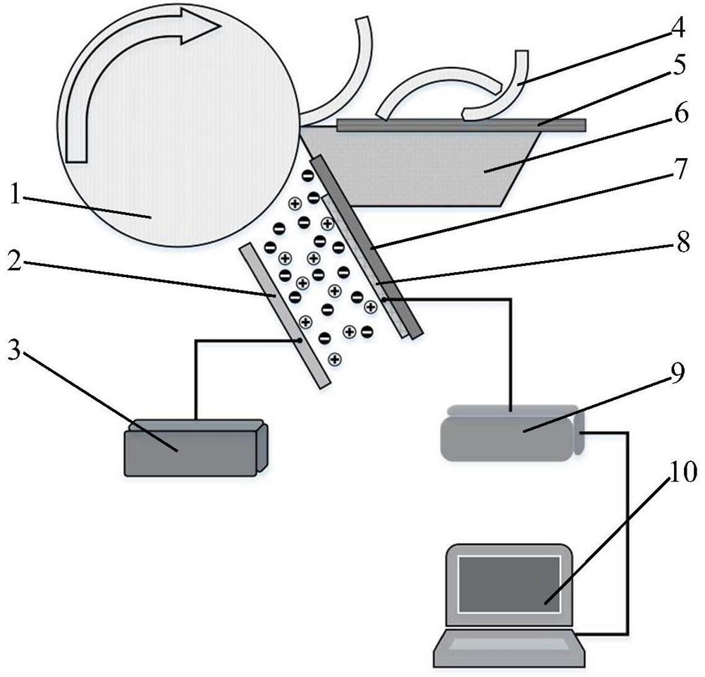
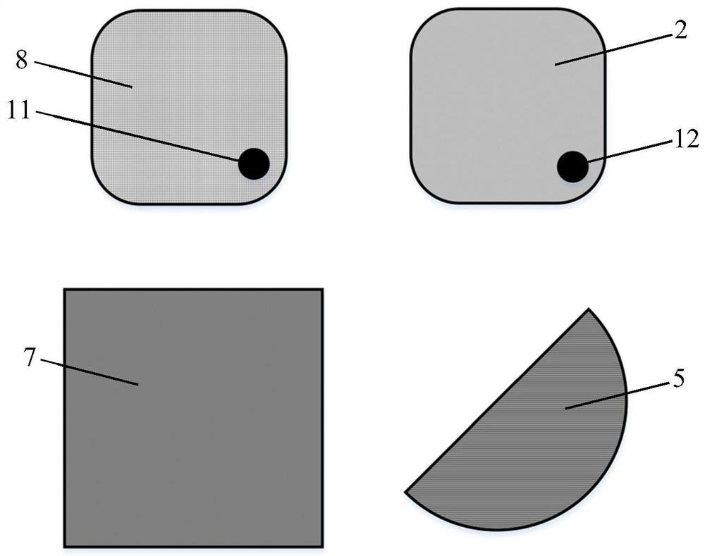
The invention provides a detection device for an escaping charged particle flow outside a cutting area, the detection device for the escaping charged particle flow outside the cutting area comprises a charged particle generation area, a charged particle flow collection device and a charged particle flow detection device, the charged particle generation area comprises a workpiece, a cutter and cuttings, the charged particle flow acquisition device is fixedly mounted on the cutter; the charged particle flow detection device consists of an electrometer, a computer, a bias electric field plate and a high-voltage electrostatic generator; the charged particle flow collecting device comprises a charged particle flow collecting plate, an insulating sheet and a chip blocking plate, a bias electric field plate is arranged on the side, away from the cutter, of the charged particle flow collecting plate, the bias electric field plate is connected with the high-voltage electrostatic generator through a bias wiring terminal, the bias electric field plate and the charged particle flow collecting plate are spaced by a certain distance, and the chip blocking plate is connected with the high-voltage electrostatic generator through the bias wiring terminal. Forming a bias electric field; the bias electric field plate is independently arranged, the influence on the measurement accuracy when bias voltage is directly applied to the acquisition plate is eliminated, and the measurement precision is improved.

Description

technical field [0001] The invention belongs to the technical field of detection equipment, and in particular relates to a detection device for a flow of charged particles escaping from a cutting area. Background technique [0002] Under different cutting processing environments, there are mutual friction, cutting, elastic / plastic deformation and even fracture of materials in the workpiece-tool contact area, resulting in the emission of charged particles in the cutting area, and the detection of the polarity and intensity of the emitted charged particles A charged particle flow collection device is required, which must have the characteristics of shielding chip interference, good insulation, and reliably distinguishing the polarity and intensity of the charged particle flow. However, there is no charged particle flow detection device with the above-mentioned characteristics at the same time under processing conditions. Japanese scholar Nakayama (document name: Triboemission...

Claims


Application Information

Patent Timeline
IPC IPC(8): G01R19/00B23Q17/00B23Q11/08
Inventor 许雪峰冯伯华胡晓冬栾志强张若冲姚伟强
Owner ZHEJIANG UNIV OF TECH
Learn More