Flow divider

A technology of shunt and constant current diode, which is applied in the directions of instruments, voltage/current isolation, and measurement of current/voltage. error, improve the accuracy of the measurement system, and achieve the effect of power amplification

Pending Publication Date: 2022-04-15
BEIJING DONGFANG MEASUREMENT & TEST INST
View PDF0 Cites 2 Cited by
  • Summary
  • Abstract
  • Description
  • Claims
  • Application Information

AI Technical Summary

Problems solved by technology

For small current shunts, especially shunts below 10mA, when the measured current is small, the resistance value of the sampling resistor is often larger. Therefore, when using an AC voltmeter to measure the output voltage of the shunt, the input impedance of the voltmeter is limited, so that The measurement error caused by the input impedance of the voltmeter will be magnified

Method used


Image

  • Flow divider
  • Flow divider
  • Flow divider

Examples


Embodiment Construction

[0034] In order to more clearly describe the embodiments of the present invention or the technical solutions in the prior art, the following will briefly introduce the drawings that are used in the embodiments. Apparently, the drawings in the following description are only some embodiments of the present invention, and those skilled in the art can also obtain other drawings according to these drawings without creative efforts.

[0035] When describing the embodiments of the present invention, the terms "vertical", "transverse", "upper", "lower", "front", "rear", "left", "right", "vertical", " The orientation or positional relationship expressed by "horizontal", "top", "bottom", "inner" and "outer" is based on the orientation or positional relationship shown in the relevant drawings, which are only for the convenience of describing the present invention and simplifying the description, and It is not to indicate or imply that the device or element referred to must have a particu...


PUM


Abstract

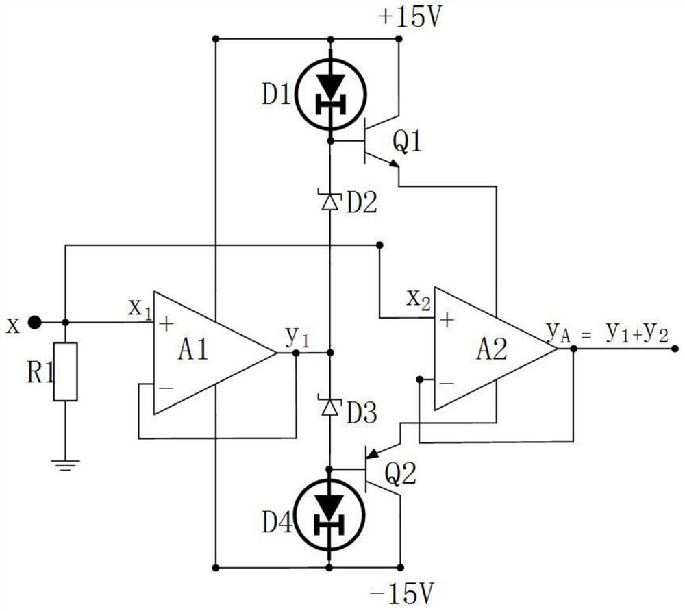
The invention relates to a shunt which comprises a first constant-current diode (D1), a second constant-current diode (D4), a first voltage-stabilizing diode (D2), a second voltage-stabilizing diode (D3), a first operational amplifier (A1) and a second operational amplifier (A2), and the first constant-current diode (D1), the first voltage-stabilizing diode (D2), the second voltage-stabilizing diode (D3) and the second constant-current diode (D4) are connected in sequence. According to the invention, the output impedance of the high-internal resistance source can be changed in a high-precision measurement system, so that the output impedance is converted into low-internal resistance output.

Description

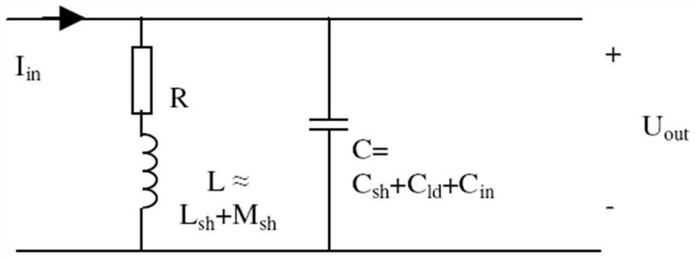
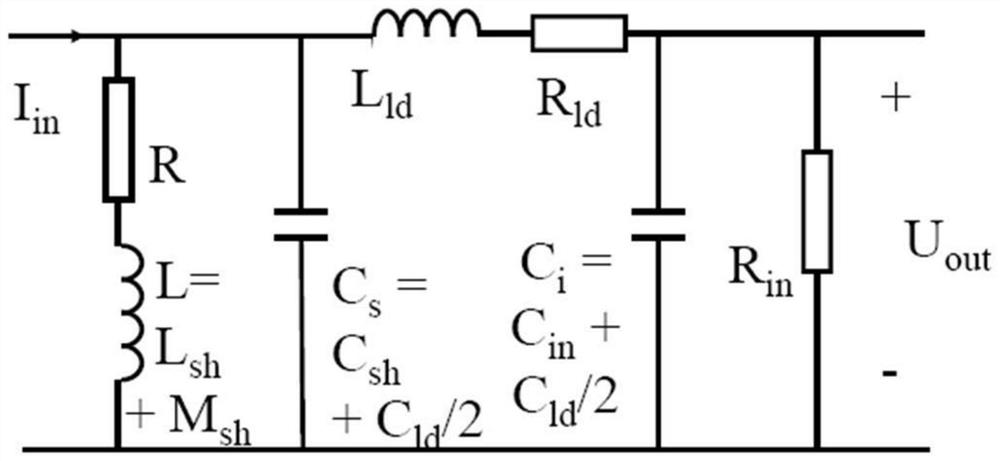
technical field [0001] The invention relates to a splitter. Background technique [0002] During the use of the shunt, a voltage measurement circuit needs to be connected in parallel to the shunt, so the impedance caused by the load effect will inevitably be introduced, resulting in measurement errors. According to the corresponding resistance value of the shunt, the output resistance of the shunt with a nominal current of 100A is 8mΩ. As the resistance of the shunt increases, the rated current will decrease accordingly. In the measurement of a small current below 10mA, The load effect is more pronounced. Therefore, the design of the shunt with a nominal current of 1mA should especially consider the influence of the load effect. [0003] The operating circuit models of shunts are mainly divided into two categories, ideal shunts and precise AC-DC shunts. Specifically, in the case of no load, the ideal shunt circuit model is as figure 2 shown. Among them, sh is the abbrev...

Claims


Application Information

Patent Timeline
Patent Type & Authority Applications(China)
IPC IPC(8): G01R19/00G01R15/14
Inventor 李晶晶游立王乾娟颜晓军候旭玮
Owner BEIJING DONGFANG MEASUREMENT & TEST INST
Why Eureka
Try Eureka