High-degree-of-freedom self-centering painting mold

A self-centering, degree-of-freedom technology, applied in electrical components, circuits, insulation of conductors/cables, etc., can solve the problems of reducing the self-positioning effect of enameled wires, aggravating bending or abrasion of enameled wires, poor automatic positioning effect, etc. Self-positioning effect, improving paint uniformity and ensuring stability

Pending Publication Date: 2022-04-15
先登高科电气股份有限公司
View PDF0 Cites 0 Cited by
  • Summary
  • Abstract
  • Description
  • Claims
  • Application Information

AI Technical Summary

Problems solved by technology

However, this structure makes the mold core only able to realize the self-positioning function in one direction, and in the other direction, it will be limited by the width of the long hole, and there is only a small movement space; thus further reducing the self-

Method used


Image

  • High-degree-of-freedom self-centering painting mold
  • High-degree-of-freedom self-centering painting mold
  • High-degree-of-freedom self-centering painting mold

Examples


Embodiment 1

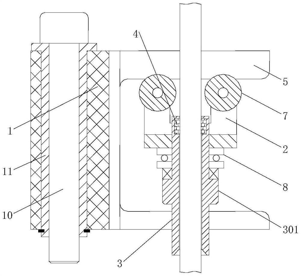
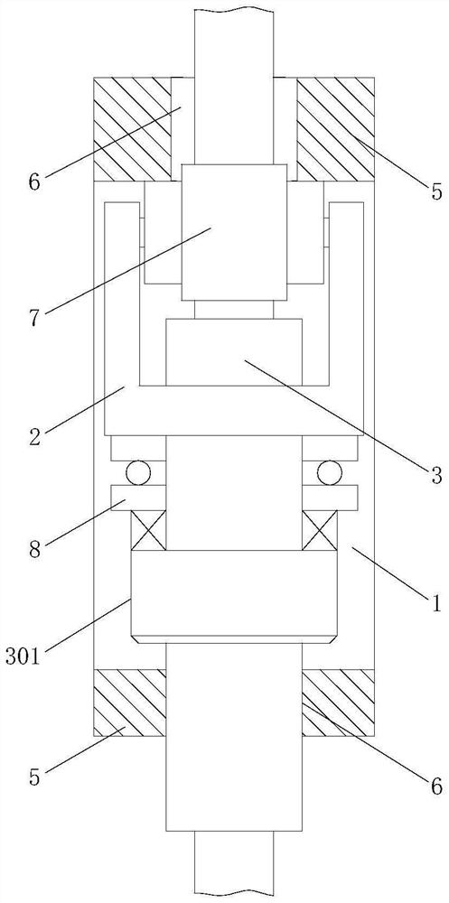
[0025] Example 1. A high degree of freedom self-centering paint mold, constituted as figure 1 with 2 As shown, it includes the positioning rod connected to the vertical painting machine. The positioning rod is located between the bottom guide rail and the upper guide roller of the vertical painting machine. The external rotation of the positioning rod is connected with the painting formwork 1, and the painting formwork 1 The upper rolling is connected with a painting mold base 2, and a mold cover 3 is arranged on the painting mold base 2. The upper end of the mold cover 3 is connected with a vertical mold core 4. Pass through the mold core 4 and enter the upper guide roller; the length of the mold sleeve 3 is 30mm, and the length of the mold core 4 is 3-5mm.

[0026] Both sides of described painting formwork 1 are all provided with slideway 5, and the middle part of slideway 5 is provided with chute 6, and one end of described painting mold base 2 is connected with rolling w...

Embodiment 2

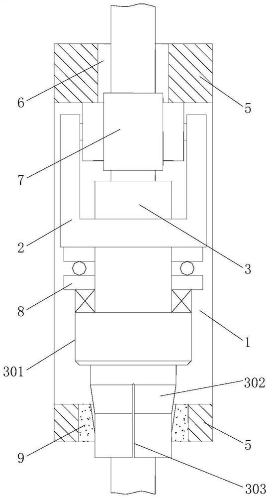
[0031] Example 2. A high degree of freedom self-centering paint mold, constituted as figure 1 with 3As shown, it includes the positioning rod connected to the vertical painting machine. The positioning rod is located between the bottom guide rail and the upper guide roller of the vertical painting machine. The external rotation of the positioning rod is connected with the painting formwork 1, and the painting formwork 1 The upper rolling is connected with the painting mold base 2, and the coating mold base 2 is provided with a mold cover 3, and the upper end of the mold cover 3 is connected with a vertical mold core 4, and the enameled wire is stretched out from the bottom guide rail when routing. Pass through the mold core 4 and enter the upper guide roller; the length of the mold sleeve 3 is 30mm, and the length of the mold core 4 is 3-5mm.

[0032] Both sides of described painting formwork 1 are all provided with slideway 5, and the middle part of slideway 5 is provided w...


PUM


Abstract

The invention discloses a high-degree-of-freedom self-centering painting mold which comprises a positioning rod connected with a vertical painting machine, a painting mold frame (1) is rotationally connected to the outer part of the positioning rod, a painting mold base (2) is connected to the painting mold frame (1) in a rolling manner, a mold sleeve (3) is arranged on the painting mold base (2), and a mold core (4) is connected to the upper end of the mold sleeve (3). The two-degree-of-freedom self-centering painting mold can achieve the two-degree-of-freedom self-centering function, sliding friction between the mold core and the painting mold frame in the moving process is reduced, and therefore the clamping stagnation problem caused by too large viscosity of a paint film is avoided, and the two-degree-of-freedom self-centering painting mold has the beneficial effects that the self-positioning effect is good, and the mold core is not prone to clamping stagnation.

Description

technical field [0001] The invention relates to a painting mold, in particular to a self-centering painting mold with a high degree of freedom. Background technique [0002] In order to improve the paint uniformity of the enameled wire, the enameled wire is usually painted with a paint mould. When in use, the paint is first applied to the surface of the copper wire by a paint roller, and then the copper wire coated with the paint film is passed through the paint. The paint mold removes the excess wire paint on the surface of the copper wire by the paint mold, so as to realize the control of the thickness of the paint film on the surface of the copper wire. However, due to the fact that there are often some angles between the guide rollers on both sides of the painting mold, and the enameled wire will also form jumps in multiple directions during the wiring process, the mold core needs to have the function of self-centering, that is, the mold It can swing arbitrarily with th...

Claims


Application Information

Patent Timeline
IPC IPC(8): H01B13/06H01B13/16
CPCH01B13/065H01B13/16
Inventor 刘蔚干胤杰叶国庆张市明王倩倩孙丽娜唐浩浩
Owner 先登高科电气股份有限公司
Why Eureka
Try Eureka