Power plant UPS grounding detection device

A power grounding and detection device technology, which is applied in the direction of power supply testing, circuit devices, and measuring device casings, can solve problems such as damage to the connection port of the detection equipment, lack of horizontal protection for the detection wire harness, and detachment of the connection end, so as to reduce the pulling force. Improve stability and prevent falling off

Inactive Publication Date: 2022-04-15
焦平
View PDF0 Cites 0 Cited by
  • Summary
  • Abstract
  • Description
  • Claims
  • Application Information

AI Technical Summary

Problems solved by technology

[0003] The UPS power structure needs to be tested during its use to ensure the normal operation of the entire circuit. Generally, multiple parameters of the UPS power structure need to be detected synchronously to judge the operation of the UPS power structure in the circuit. The parameters need to be connected to different detection harnesses. Since the structure of the UPS power supply needs to be tested frequently, there are multiple detection harnesses connected to the surface of the testing equipment, and they are pulled back and forth for a long time in a small space box, so that the detection harness and the detection end are synchronized. Pulling will easily lead to the detachment of the connecting end, and the detection wire harness lacks horizontal protection when pulling, so that it will exert a vertical pull on the connecting end when the detection equipment moves, which will easily cause damage to the connection port of the detection equipment. , we propose a power plant UPS power grounding detection device

Method used


Image

  • Power plant UPS grounding detection device
  • Power plant UPS grounding detection device
  • Power plant UPS grounding detection device

Examples


Embodiment 1

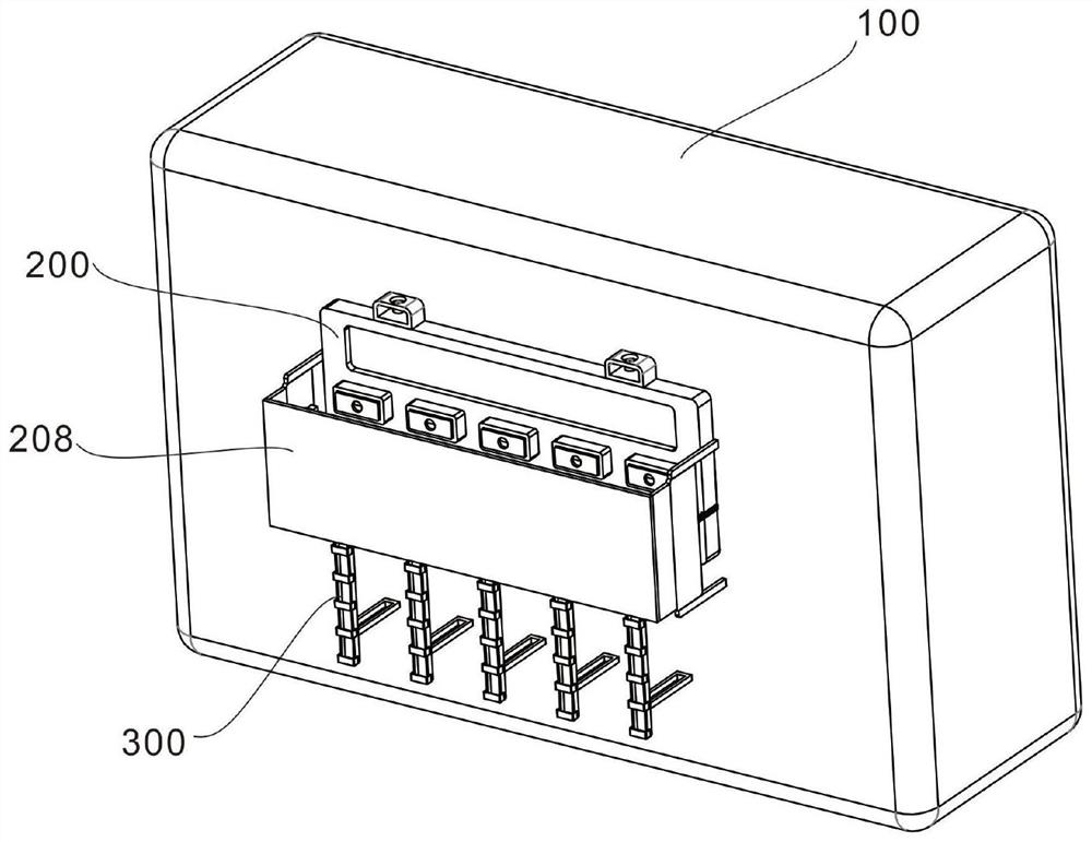
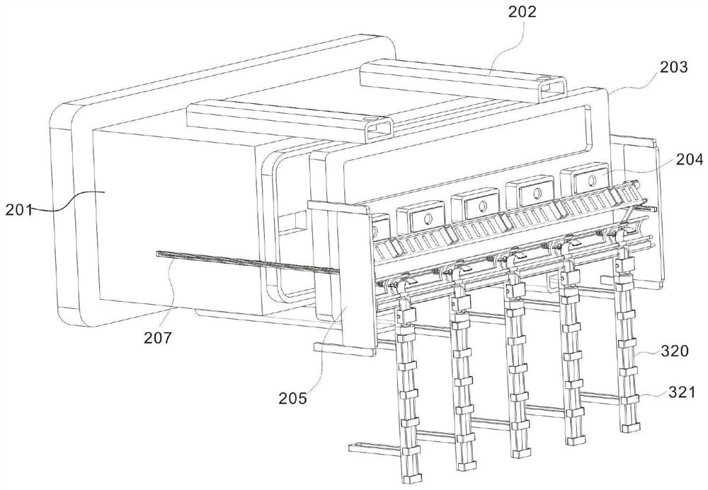
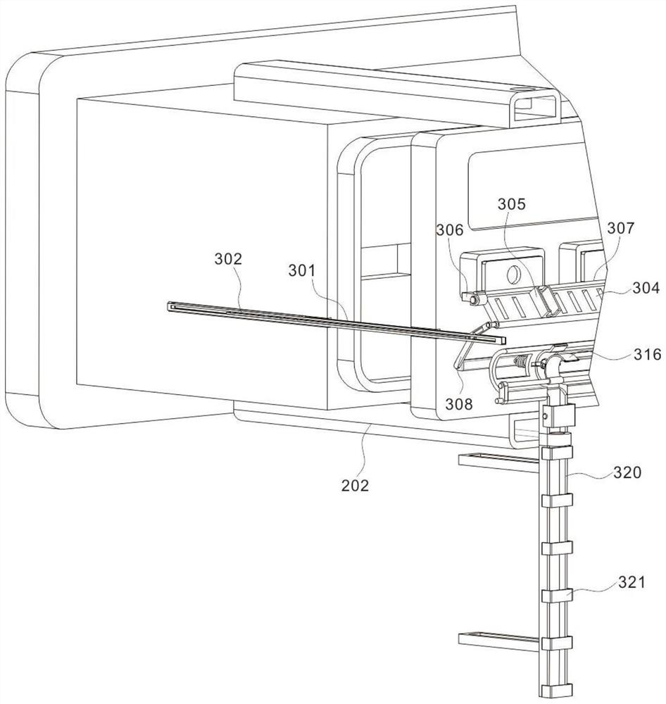
[0026] Example 1: Please refer to figure 1 , The present invention provides a power plant UPS power supply grounding detection device, including a box body 100, the box body 100 has a UPS power supply structure; a bearing assembly 200, including a detection device 201, the top surface of the detection device 201 is symmetrically provided with a connection plate 202, the connection plate The end portion of 202 is fixedly connected to the carrier board 203, and the carrier board 203 is linearly and evenly arranged with connecting structures 204; the follow-up protection component 300 is arranged on one side of the carrier board 203, and the follow-up protection component 300 includes an upper and lower part. The double rack structure 301 is provided, and the pinion gear 302 is meshed and connected between the double rack structures 301 .

[0027] see figure 2 , the two side walls of the carrier plate 203 are fixedly connected to the support plate 205, the surface of the suppor...

Embodiment 2

[0028] Example 2: Please refer to Figure 2-4 , in the double rack structure 301, the other end of the rack on the other side is movably connected with one end of the upper link 303, the other end of the upper link 303 is movably connected with the lower end of the wire support plate 304, and the upper end of the wire support plate 304 is connected by a rotating connector 306 and the rotating shaft 307 are rotatably connected to the bottom surface of the connection structure 204. When the detection device 201 is pulled out, the double rack structure 301 is driven to move on the guide rail 207, the upper link 303 is pulled to swing upward, and the wire support plate 304 is driven upward synchronously. pendulum, the cable support plate 304 is provided with concave clamping blocks 305 corresponding to the positions of the connecting structure 204 at equal distances.

[0029] The bottom end of the upper link 303 is movably connected to the lower link 308, and the bottom end of the...


PUM


Abstract

The invention discloses a power plant UPS grounding detection device in the technical field of power plant equipment. Connecting plates are symmetrically arranged on the top surface of the detection equipment, the end parts of the connecting plates are fixedly connected with a bearing plate, and connecting structures are linearly and uniformly arranged on the bearing plate; the follow-up protection assembly is arranged on one side of the bearing plate; when the detection equipment is pulled out, the double-rack structure is driven to move on the guide rail, the upper connecting rod is pulled to swing upwards, the wire supporting wire is driven to swing upwards synchronously, the movable arc plate is pushed and rotated to be separated from the fixed arc plate, and clamping of the detection wire harness is relieved; the pulling force generated on the connecting end when the detection wire harness moves is offset, the problem that the connecting port of the detection equipment is damaged is avoided, the pulling force borne by the detection wire harness when the detection equipment is pulled out is reduced, the problem that the detection wire harness falls off is avoided, and the stability of the connecting end of the detection equipment is improved.

Description

technical field [0001] The invention relates to the technical field of power plant equipment, in particular to a grounding detection device for a UPS power supply in a power plant. Background technique [0002] A power plant is a power plant that converts some form of raw energy into electrical energy for stationary or transportation use, such as thermal, hydro, steam, diesel or nuclear power plants. The UPS power supply structure generally includes: a UPS power supply and a programmable logic controller PLC connected to the UPS power supply, and one end of the UPS power supply is connected to the input line, and the other end is connected to the wind turbine through the output line. [0003] The UPS power supply structure needs to be tested during use to ensure the normal operation of the entire circuit. Generally, it is necessary to perform synchronous detection on multiple parameters of the UPS power supply structure to determine the operation of the UPS power supply stru...

Claims


Application Information

Patent Timeline
IPC IPC(8): H02G3/04H02G3/32H02J9/00H02J9/06G01R31/40G01R1/04
CPCH02G3/045H02G3/0456H02G3/32H02J9/00H02J9/06G01R31/40G01R1/04
Inventor 焦平连江连宏伟辛宇
Owner 焦平
Why Eureka
Try Eureka