
Oscillating head type milling and turning combined machining center

A compound machining center and swing head technology, applied in metal processing, metal processing equipment, metal processing machinery parts, etc., can solve the problems of restricting the processing quality and efficiency of high-end parts, comprehensive compensation processing difficulties, etc., and achieve real-time dynamic solution of multiple errors The effects of comprehensive compensation processing, large torque, and large power

Active Publication Date: 2022-04-19
SHANDONG MACHINERY DESIGN INST
View PDF10 Cites 2 Cited by
  • Summary
  • Abstract
  • Description
  • Claims
  • Application Information

AI Technical Summary

Problems solved by technology

At present, the disclosed milling-turning or turning-milling compound machining center has played a positive role in improving my country's multi-axis linkage processing technology. However, the structure of the existing compound machining center is very difficult to realize multi-error real-time dynamic comprehensive compensation processing, which restricts high-end parts. processing quality and efficiency

Method used


Image

  • Oscillating head type milling and turning combined machining center
  • Oscillating head type milling and turning combined machining center
  • Oscillating head type milling and turning combined machining center

Examples


Embodiment Construction

[0021] In order to make the present invention more clear and understandable, the technical solution of the present invention will be further described in detail below in conjunction with the accompanying drawings and examples. All examples.

[0022] In this article, terms such as "left, right, front, and back" are established based on the positional relationship shown in the drawings. Depending on the drawings, the corresponding positional relationship may also change accordingly. It is understood as an absolute limitation of the scope of protection.

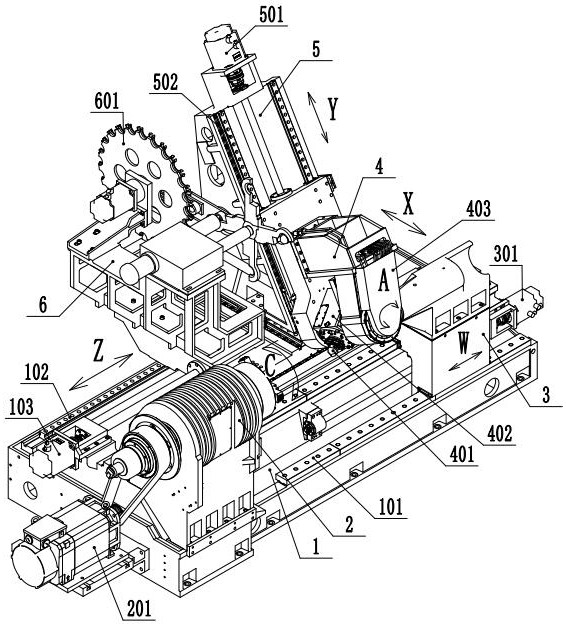
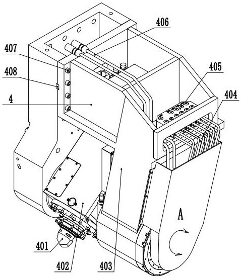
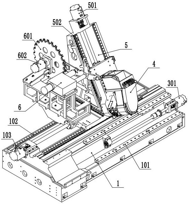
[0023] combine Figure 1-4 , a swing head type milling and turning compound machining center, comprising a bed base 1, a turning head 2, a tailstock 3, a swing head 4, a ram 5 and a tool magazine 6, the turning head 2 is fixedly installed on the bed base 1, and the main shaft Driven by the motor 201, the turning head 2 has interpolation and positioning functions, which is called the C axis; the tailstock 3 is slidingly connect...


PUM


Abstract

The invention provides a swing head type milling and turning combined machining center which comprises a lathe base, a turning head, a tailstock, a swing head, a ram and a tool magazine, the turning head is fixedly installed at the left end of the lathe base, the tailstock is installed at the right end of the lathe base in a sliding mode, the turning head and the tailstock are oppositely arranged, the ram is arranged on the lathe base in a sliding mode, and the ram is located on one side of the turning head and the tailstock. The ram comprises a large sliding plate, a ram body and a small sliding plate, the ram body is arranged on the large sliding plate in a sliding mode, the small sliding plate is arranged on the front end face of the ram body in a sliding mode, the tool magazine is fixedly installed on the large sliding plate and located on the left side of the ram body, and the swing head is fixedly installed on the small sliding plate. The swing head is light in structure, high in precision, fast in response and large in torque, a solid foundation is laid for development of high-grade numerical control machine tools, and meanwhile the swing head is a milling and turning combined machining center of a six-shaft structure and can solve the problem of multi-error real-time dynamic comprehensive compensation machining.

Description

technical field [0001] The invention relates to the field of numerical control processing equipment, in particular to a swing head type milling and turning compound processing center. Background technique [0002] High-end CNC machine tools have functional characteristics such as high speed, precision, intelligence, compounding, multi-axis linkage and network communication, and their development level is an important symbol of the country's modern industrialization. At present, the disclosed milling-turning or turning-milling compound machining center has played a positive role in improving my country's multi-axis linkage processing technology. However, the structure of the existing compound machining center is very difficult to realize multi-error real-time dynamic comprehensive compensation processing, which restricts high-end parts. processing quality and efficiency. Contents of the invention [0003] In order to solve the problems in the background technology, the pres...

Claims


Application Information

Patent Timeline
Patent Type & Authority Applications(China)
IPC IPC(8): B23Q37/00B23Q1/25B23Q5/36
CPCB23Q37/00B23Q1/25B23Q5/36Y02P70/10
Inventor 王加祥国兴洋胡明王桂东
Owner SHANDONG MACHINERY DESIGN INST
Learn More