Pushing equipment for lead frame processing

A lead frame and equipment technology, applied in conveyor objects, cleaning methods and utensils, cleaning methods using tools, etc., can solve problems such as reduced processing efficiency, increased time, residues, etc., to ensure cleaning effect and facilitate high control. Effect

Pending Publication Date: 2022-04-19
铜陵蓝盾丰山微电子有限公司
View PDF1 Cites 0 Cited by
  • Summary
  • Abstract
  • Description
  • Claims
  • Application Information

AI Technical Summary

Problems solved by technology

[0003] Patent Publication No.: CN213124403U is a lead frame pushing device. When the turntable rotates, it will drive the threaded rod to rotate through the cooperation of the bearing, which can adjust the height of the device and improve the practicability of the device. At the same time, the lead frame is pushed When the board is pushed, it will pass under the brush, and the brush will wipe the dust on the surface of the lead frame through the fixing of the fixed plate and the brush plate, which can have a cleaning function and improve work efficiency. During the cleaning process, it is easy to cause the residue of the brush on the surface of the lead frame, the cleaning efficiency is not high, and the brush plate and the brush cannot be removed, and the lead frame is manually lifted, which increases the time and reduces the processing efficiency

Method used


Image

  • Pushing equipment for lead frame processing
  • Pushing equipment for lead frame processing
  • Pushing equipment for lead frame processing

Examples


Embodiment Construction

[0024] In order to further explain the technical means and effects of the present invention to achieve the intended purpose of the invention, the specific implementation, structure, features and effects of the present invention will be described in detail below in conjunction with the accompanying drawings and preferred embodiments.

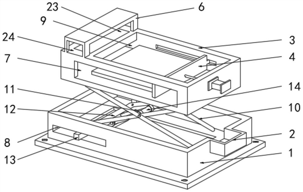
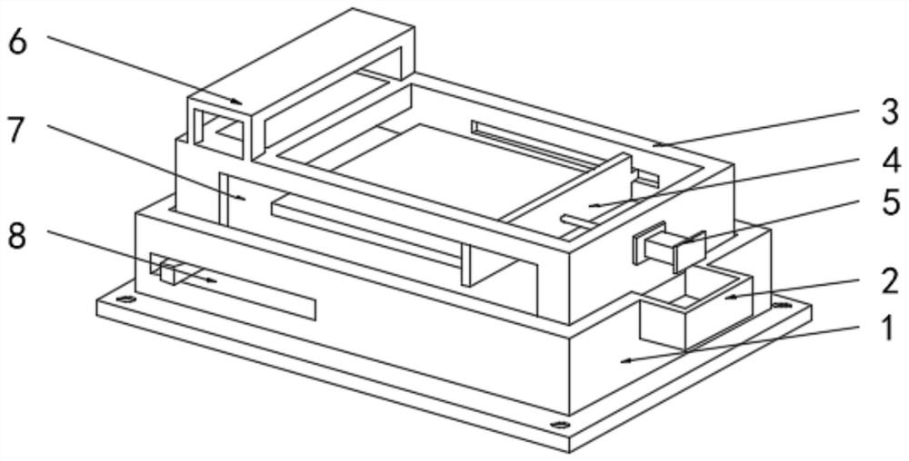
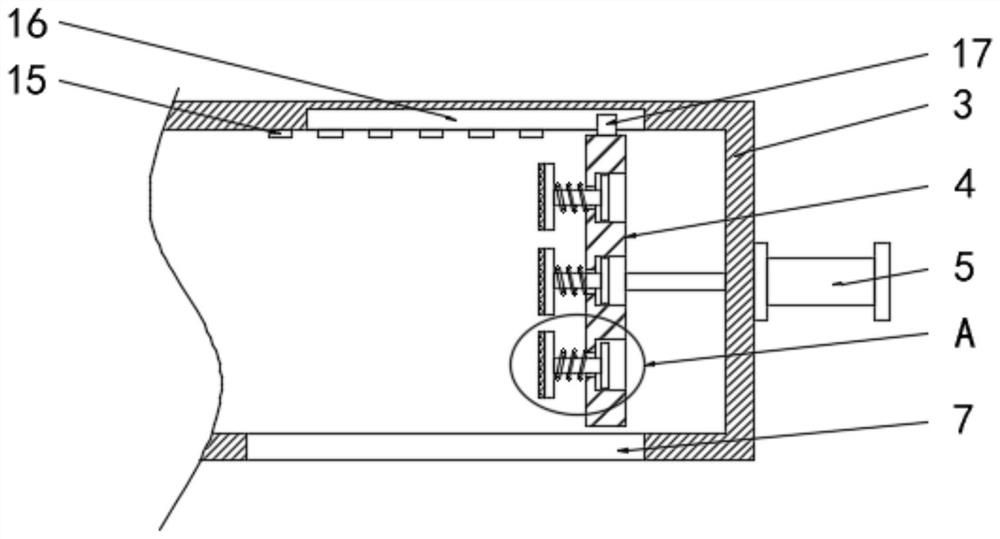
[0025] see Figure 1-Figure 5 As shown, the pushing equipment for lead frame processing includes a base 1, a lifting mechanism is installed on the top surface of the base 1, and a pushing seat 3 for accommodating the lead frame is movably connected to the top surface of the lifting mechanism. There is a fixed seat 6, and one side surface of the pusher seat 3 is provided with a feed port 7 for the lead frame to enter, and the inside of the pusher seat 3 is provided with an obliquely arranged discharge port 9 near the bottom of the fixed seat 6, and The bottom of the top surface of the pushing seat 3 corresponding to the fixed seat 6 is provided wi...


PUM


Abstract

The invention discloses pushing equipment for lead frame processing, and particularly relates to the technical field of lead frame processing equipment.The top surface of a base is provided with a lifting mechanism, and the top surface of the lifting mechanism is movably connected with a pushing seat used for containing a lead frame; by arranging the cleaning mechanism, the surface of a lead frame is swept and scraped in a rolling mode while the lead frame is discharged, dust on the surface of the lead frame is attached to the surface of a hair sticking roller, cleanliness of the surface of the lead frame is guaranteed, a pull block is pulled through a notch, two transmission vertical plates are opened, and the hair sticking roller falls off; the surface of the hair collecting roller can be cleaned or replaced conveniently, and the cleaning effect of the lead frame is guaranteed; in the pushing process, the multiple rubber pads are attached to the side face of the lead frame, one end of the T-shaped block extrudes the compression spring, the lead frame is elastically pushed, and the integrity of the side face of the lead frame is guaranteed. The hydraulic cylinder pushes the lifting frame to move, lifting opening of the material pushing base is achieved, and height control over the material pushing base is facilitated.

Description

technical field [0001] The invention relates to the technical field of lead frame processing equipment, in particular to a pushing device for lead frame processing. Background technique [0002] In the field of integrated circuits, it is generally necessary to use a semiconductor lead frame as the carrier of an integrated circuit chip. The semiconductor lead frame uses bonding materials such as gold wire, aluminum wire, and copper wire to realize the electrical connection between the lead-out end of the chip's internal circuit and the outer lead to form an electrical connection. The key structural part of the circuit, which acts as a bridge connecting with external wires. [0003] Patent Publication No.: CN213124403U is a lead frame pushing device. When the turntable rotates, it will drive the threaded rod to rotate through the cooperation of the bearing, which can adjust the height of the device and improve the practicability of the device. At the same time, the lead frame ...

Claims


Application Information

Patent Timeline
IPC IPC(8): B65G47/82B08B1/02B08B7/00
CPCB65G47/82B08B7/0028B08B1/165B08B1/20
Inventor 马春晖朱宝才陆辉辉陈亮窦坤朱亮
Owner 铜陵蓝盾丰山微电子有限公司
Why Eureka
Try Eureka