Intermediate shaft brake

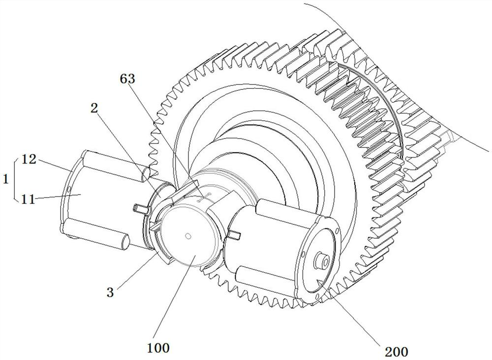
An intermediate shaft and brake technology, applied in the field of vehicles, can solve the problems of residual braking, drag loss, the inability of the steel plate and the friction plate to separate quickly, and achieve the effect of avoiding residual braking and large braking torque

Active Publication Date: 2022-04-19
FAW JIEFANG AUTOMOTIVE CO
View PDF15 Cites 2 Cited by
  • Summary
  • Abstract
  • Description
  • Claims
  • Application Information

AI Technical Summary

Problems solved by technology

[0004] The purpose of the present invention is to provide an intermediate shaft brake to solve the problem that the intermediate shaft brake in the related art adopts a multi-piece wet brake plate group structure, and the friction plates keep relative movement with respect to the steel plate at all times when the brake is not working, causing Unnecessary drag loss, at the same time, during the brake release process, the steel plate and the friction plate cannot be separated quickly due to the oil film effect, causing unnecessary residual braking problems

Method used


Image

  • Intermediate shaft brake
  • Intermediate shaft brake
  • Intermediate shaft brake

Examples


Embodiment Construction

[0044]The technical solutions of the present invention will be clearly and completely described below in conjunction with the accompanying drawings. Apparently, the described embodiments are some of the embodiments of the present invention, but not all of them. Based on the embodiments of the present invention, all other embodiments obtained by persons of ordinary skill in the art without making creative efforts belong to the protection scope of the present invention.

[0045] In the description of the present invention, it should be noted that the terms "center", "upper", "lower", "left", "right", "vertical", "horizontal", "inner", "outer" etc. The indicated orientation or positional relationship is based on the orientation or positional relationship shown in the drawings, and is only for the convenience of describing the present invention and simplifying the description, rather than indicating or implying that the referred device or element must have a specific orientation, o...


PUM


Abstract

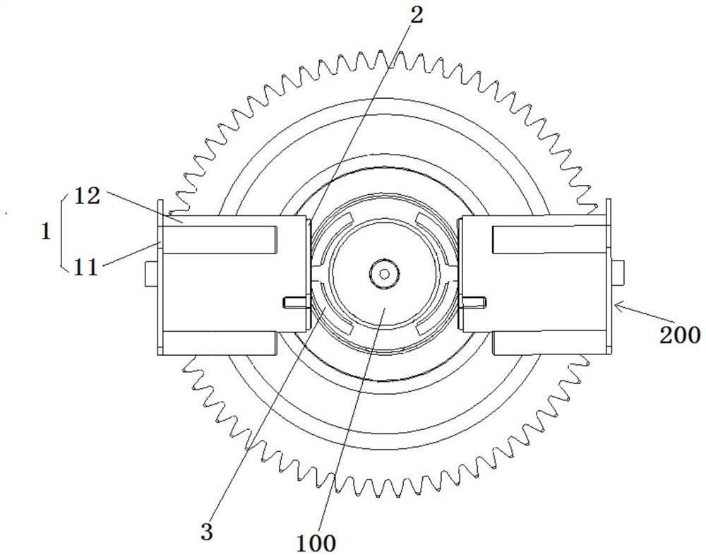
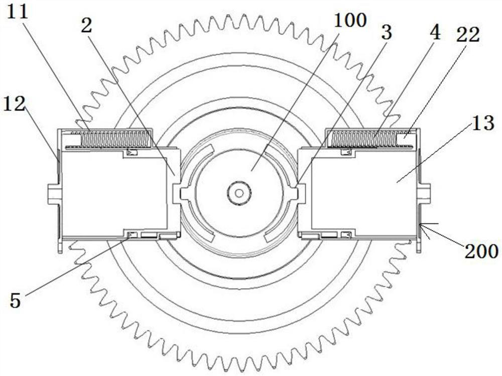
The invention relates to the technical field of vehicles, in particular to an intermediate shaft brake which comprises an intermediate shaft and two dual friction assemblies, and the two dual friction assemblies are oppositely arranged on the two sides of the radial direction of the intermediate shaft in a spaced mode. The dual friction assembly comprises an air cylinder shell, a piston, a dual friction block and a return spring. The dual friction block is connected to the piston, the piston can slide relative to the air cylinder shell and is provided with a braking position and a non-braking position, when the piston is located at the braking position, the dual friction block is attached to the intermediate shaft, and when the piston is located at the non-braking position, the dual friction block is separated from the intermediate shaft and cannot be affected by an oil film, residual braking is avoided, and the service life of the piston is prolonged. And high-pressure gas input into the piston cavity from the high-pressure gas source can drive the piston to move to the braking position from the non-braking position, and the return spring can drive the piston to move to the non-braking position from the braking position.

Description

technical field [0001] The invention relates to the technical field of vehicles, in particular to an intermediate shaft brake. Background technique [0002] In the AMT market of heavy-duty commercial vehicles at home and abroad, the intermediate shaft brakes are in the form of multi-piece wet brake pads, and the cylinder pistons are arranged axially, and the pistons are in direct contact with the gear oil. In terms of reliability, this traditional multi-piece wet brake pad set structure has very high requirements for heat dissipation. [0003] For example, the previous patent with the application number CN201921107831.3 provides an intermediate shaft brake, which includes a brake housing, a piston, a friction plate and a steel plate. There is a brake groove matching with the steel claw in the direction, and a positioning steel plate is installed on the installation end surface of the brake housing. The positioning steel plate includes the positioning steel plate body, and t...

Claims


Application Information

Patent Timeline
Patent Type & Authority Applications(China)
IPC IPC(8): F16D51/24F16H57/04
CPCF16D51/24F16H57/043F16D2121/04Y02E10/72
Inventor 赵达高志飞孙安邦王巍巍
Owner FAW JIEFANG AUTOMOTIVE CO
Why Eureka
Try Eureka