
Combined Electromagnetic Switching Valve and Its Air Conditioning System

An electromagnetic switching valve, combined technology, applied in the direction of multi-way valve, valve device, valve details, etc., can solve the problems of dirty blockage, ice blockage, high cost, etc., and achieve the effect of cost saving and energy consumption reduction

Active Publication Date: 2019-06-11
ZHEJIANG DUNAN ARTIFICIAL ENVIRONMENT
View PDF5 Cites 0 Cited by
  • Summary
  • Abstract
  • Description
  • Claims
  • Application Information

AI Technical Summary

Problems solved by technology

Now to solve this problem, one is to connect a one-way valve to the auxiliary cooler, and connect a capillary tube to the outlet of the outdoor heat exchanger in parallel with the reverse inlet of the one-way valve to the outlet of the outdoor heat exchanger, so that the refrigerant enters during heating If the one-way valve is blocked, it will enter the outlet of the outdoor heat exchanger through this capillary, but this method will cause flow resistance, resulting in excessive pressure drop in the system, and there is a risk of dirt blockage and ice blockage; the second is to connect two solenoid valves in parallel. The cost is too high and the electronic control scheme needs to be changed

Method used


Image

  • Combined Electromagnetic Switching Valve and Its Air Conditioning System
  • Combined Electromagnetic Switching Valve and Its Air Conditioning System
  • Combined Electromagnetic Switching Valve and Its Air Conditioning System

Examples


Embodiment Construction

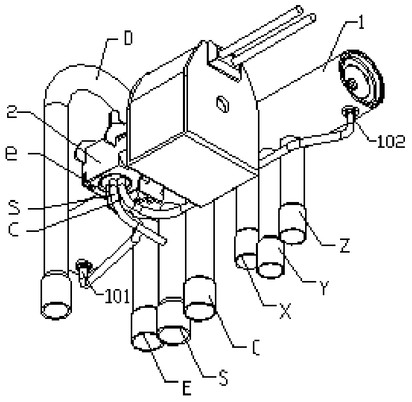
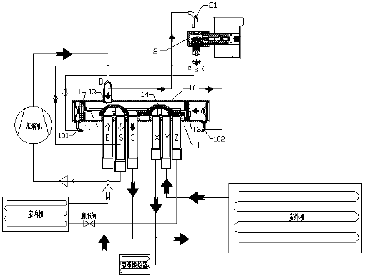
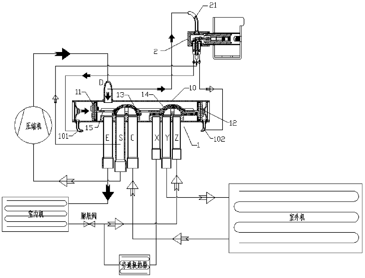
[0021] Such as Figure 1 to Figure 3 As shown, the combined electromagnetic switching valve includes a valve body 10, and a first piston assembly 11 and a second piston assembly 12 are respectively provided at both ends of the valve body cavity, and the gap between the first piston assembly and the corresponding valve body end cover is A first pressure chamber is formed, a second pressure chamber is formed between the second piston assembly and the corresponding valve body end cover, an intermediate pressure chamber is formed between the first piston assembly and the second piston assembly, and a A slide block is arranged, and the slide block is connected with the first piston assembly and the second piston assembly, and the slide block comprises a first slide block 13 and a second slide block 14, and the first slide block and the second slide block are installed on On the same guide frame 15, the first slider 13 and the second slider 14 are driven by the first piston assembly...


PUM


Abstract

The invention discloses a combined electromagnetic switching valve and its air-conditioning system. The combined electromagnetic switching valve includes a valve body, and a first piston assembly and a second piston assembly are respectively arranged at both ends of the inner chamber of the valve body. The first piston assembly A first pressure chamber is formed between the corresponding valve body end cover, a second pressure chamber is formed between the second piston assembly and the corresponding valve body end cover, and an intermediate piston assembly is formed between the first piston assembly and the second piston assembly. A pressure chamber, a slide block is provided in the middle pressure chamber, the slide block is connected with the first piston assembly and the second piston assembly, the slide block includes a first slide block and a second slide block, the middle pressure chamber is connected There are E takeover, S takeover, C takeover, D takeover, X takeover, Y takeover, and Z takeover. The present invention uses the high-low pressure difference in the air-conditioning system to automatically switch the refrigerant flow direction through the drive switching of the pilot valve, and realizes the switching of the operating state of the air-conditioning system without providing an additional power source and will not cause a large resistance loss, thus saving costs. , reducing energy consumption.

Description

technical field [0001] The present invention relates to air conditioning systems. Background technique [0002] At present, energy-saving air-conditioning products need to perform functional heat exchange (such as heat recovery, electronic control module cooling, economizer, etc.) Toggle split. Now to solve this problem, one is to connect a one-way valve to the auxiliary cooler, and connect a capillary tube to the outlet of the outdoor heat exchanger in parallel with the reverse inlet of the one-way valve to the outlet of the outdoor heat exchanger, so that the refrigerant enters during heating If the one-way valve is blocked, it will enter the outlet of the outdoor heat exchanger through this capillary, but this method will cause flow resistance, resulting in excessive pressure drop in the system, and there is a risk of dirt blockage and ice blockage; the second is to connect two solenoid valves in parallel. The cost is too high, and the electric control scheme needs to b...

Claims


Application Information

Patent Timeline
Patent Type & Authority Patents(China)
IPC IPC(8): F16K11/065F16K31/06F16K31/124F25B41/04F25B41/20
CPCF16K11/065F16K31/0603F16K31/124F25B41/20
Inventor 胡煜刚王定军
Owner ZHEJIANG DUNAN ARTIFICIAL ENVIRONMENT
Learn More