
A pressurized high-level fuel tank with small oil supply pressure loss

A high-level fuel tank and pressure technology, applied in the direction of fuel supply tank device, fluid pressure actuation device, fluid pressure actuation system components, etc., can solve problems such as increased viscosity, increased construction cost, and outflow of lubricating oil.

Active Publication Date: 2017-01-25
CHENGDU CHENGFA SCI & TECH POWER ENG
View PDF5 Cites 0 Cited by
  • Summary
  • Abstract
  • Description
  • Claims
  • Application Information

AI Technical Summary

Problems solved by technology

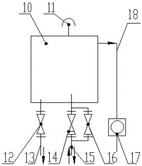
[0009] 1. During the stand-alone debugging and start-up process of the host equipment, the existing high-level fuel tank is under the condition that the lubricating oil supply pressure or flow is relatively large, and the lubricating oil has no time to flow out from the oil return pipe 18, resulting in overflow from the air filter 11 of the high-level fuel tank, resulting in lubricating oil Waste of oil, and cause pollution to the high oil tank and the environment
If it is necessary to avoid this situation, there are two solutions: the first way, pay close attention to the outlet of the air filter 11 and the oil return peep port 17 of the high fuel tank, and turn it down or close it in time when there is lubricating oil overflowing Bypass switch valve 16; however, it is cumbersome to operate in actual engineering and does not conform to the principles of man-machine design; the second method is to design a liquid level sensor on the top of the high-level fuel tank and design the bypass switch valve 16 as an electric regulating valve Or electric switching valve, interlocking automatic control bypass switching valve 16, this will undoubtedly increase the cost input of the system
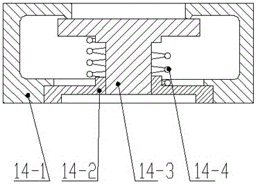
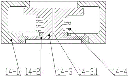
[0010] 2. When the host equipment needs emergency lubrication, when the lubricating oil in the existing high-level oil tank passes through the check valve 14 under the action of gravity, in addition to the inevitable pressure loss caused by the on-site pipeline layout, there are also problems that need to be overcome. The spring force of the spring 14-4 of the one-way valve 14 has certain resistance loss, which is unfavorable for the lubrication of the main engine; even sometimes the gravity produced by the height of the liquid level is not enough to overcome the spring force of the one-way valve 14, and the one-way valve 14 The disc 14-3 of the valve is closed under the spring force of the spring 14-4. At this time, the remaining lubricating oil in the box 10 can only pass through the through hole 14-3.1 of the disc 14-3 of the one-way valve 14 to the host equipment. Lubrication, the lubricating effect through the through hole 14-3.1 is limited. If this pressure loss is to be compensated, the installation height of the high oil tank needs to be increased, or the volume of the oil tank should be increased, which will also lead to an increase in system cost
[0011] 3. When the ambient temperature is very low, since the circulating flow of lubricating hot oil in the tank 10 from the oil station through the through hole 14-3.1 of the disc 14-3 of the check valve 14 is very small, the tank 10 will The temperature of the lubricating oil is low, the viscosity becomes larger or condensation occurs. At this time, if the system needs emergency lubrication, it cannot play the role of emergency lubrication; in order to solve this problem, on the one hand, in order to avoid blockage and condensation, then It is necessary to increase the diameter of the small hole 14-3 on the disc 14-3 of the one-way valve 14, thereby increasing the overflow of lubricating oil in the high-level oil tank, but it will cause the loss of system flow and energy consumption; on the other hand, the high-level oil tank and Its pipelines are covered with antifreeze, which will undoubtedly lead to an increase in construction costs

Method used


Image

  • A pressurized high-level fuel tank with small oil supply pressure loss
  • A pressurized high-level fuel tank with small oil supply pressure loss
  • A pressurized high-level fuel tank with small oil supply pressure loss

Examples


Embodiment 1

[0038] Such as Figure 4 and 5 As shown, the present invention provides a pressurized high-level fuel tank with a small oil supply pressure loss, including a tank body 10, the bottom of the tank body 10 is provided with a drain pipe 13 and a working oil pipe 15, and the drain pipe 13 is provided with The blowdown valve 12 is characterized in that the working oil pipe 15 is provided with an on-off control valve 5, the top of the box 10 is provided with a connecting pipe 1, and the connecting pipe 1 is provided with a throttling orifice group 2 for throttling The orifice plate group 2 is connected with a pre-pressurized air filter 3 through an overflow pipe 4. An overflow port 4-1 is provided on the middle side of the overflow pipe 4, and an oil return pipe 18 is connected to the overflow port 4-1. The oil return pipe 18 is provided with an oil return peek port 17 .

[0039] In this embodiment, the arrangement of the throttling orifice group 2 and the pre-pressurized air filte...

Embodiment 2

[0042] Such as Figures 4 to 6 As shown, the present invention provides a pressurized high-level fuel tank with a small oil supply pressure loss, including a tank body 10, the bottom of the tank body 10 is provided with a drain pipe 13 and a working oil pipe 15, and the drain pipe 13 is provided with The blowdown valve 12 is characterized in that the working oil pipe 15 is provided with an on-off control valve 5, the top of the box 10 is provided with a connecting pipe 1, and the connecting pipe 1 is provided with a throttling orifice group 2 for throttling The orifice plate group 2 is connected with a pre-pressurized air filter 3 through an overflow pipe 4. An overflow port 4-1 is provided on the middle side of the overflow pipe 4, and an oil return pipe 18 is connected to the overflow port 4-1. The oil return pipe 18 is provided with an oil return peek port 17 .

[0043] The throttle orifice group 2 includes an upper orifice 2-1 and a lower orifice 2-3, and a channel pipe 2...

Embodiment 3

[0045] Such as Figures 4 to 8 As shown, the present invention provides a pressurized high-level fuel tank with a small oil supply pressure loss, including a tank body 10, the bottom of the tank body 10 is provided with a drain pipe 13 and a working oil pipe 15, and the drain pipe 13 is provided with The blowdown valve 12 is characterized in that the working oil pipe 15 is provided with an on-off control valve 5, the top of the box 10 is provided with a connecting pipe 1, and the connecting pipe 1 is provided with a throttling orifice group 2 for throttling The orifice plate group 2 is connected with a pre-pressurized air filter 3 through an overflow pipe 4. An overflow port 4-1 is provided on the middle side of the overflow pipe 4, and an oil return pipe 18 is connected to the overflow port 4-1. The oil return pipe 18 is provided with an oil return peek port 17 .

[0046] The throttle orifice group 2 includes an upper orifice 2-1 and a lower orifice 2-3, and a channel pipe 2...


PUM


Abstract

The invention discloses a high-level oil tank with pressure and low oil supply pressure losses. The high-level oil tank solves the technical problems that lubricating oil is wasted and the environment is polluted due to the fact that the lubricating oil overflows from an air filter on the condition that the lubricating oil in an existing high-level oil tank is high in oil supply pressure, and emergent lubrication is not facilitated due to the fact that the lubricating oil in a tank body of the existing high-level oil tank needs to overcome spring force of a spring inside a one-way valve and resistance is lost during emergent lubrication. The high-level oil tank comprises a tank body. The bottom of the tank body is provided with a blow-off pipe and a working oil pipe. A blow-off valve is arranged on the blow-off pipe. A switching control valve is arranged on a working oil pipe. A connecting pipe is arranged on the top of the tank body. A throttling orifice set is arranged on the connecting pipe and connected with a prepressing type air filter through an overflowing pipe. An overflowing opening is formed in one side of the middle of the overflowing pipe and connected with an oil return pipe. An oil return peeping opening is formed in the oil return pipe. The high-level oil tank has the beneficial effects of being low in oil supply pressure loss, safe and environmentally friendly.

Description

technical field [0001] The invention relates to the field of high-level oil tanks commonly used in lubricating oil systems, shaft sealing oil systems, etc., and more specifically relates to a high-level oil tank under pressure with small oil supply pressure loss. Background technique [0002] The high-level oil tank is a spare emergency oil tank used in emergencies such as compressors, turbines, gear transmissions, pumps and drivers; when the lubricating oil system, shaft sealing oil system and control oil system fail, during the equipment deceleration process The medium and high oil tanks are a preventive measure to ensure the safe shutdown of the equipment. They are used to ensure sufficient supply of lubricating oil, sealing oil and control oil, and can effectively prevent equipment damage. [0003] Such as Figures 1 to 3 As shown, the existing high-level oil tank includes a box body 10, an air filter 11 is arranged on the box body 10, and a sewage discharge pipe 13, a w...

Claims


Application Information

Patent Timeline
Patent Type & Authority Patents(China)
IPC IPC(8): F15B1/26F15B21/04
Inventor 唐翠蓉文豪黄晓红
Owner CHENGDU CHENGFA SCI & TECH POWER ENG
Learn More