Passive optical network architecture and inter-ONU communication method based on same

A technology of passive optical network and communication method, which is applied in the field of passive optical network and passive optical network architecture, can solve problems such as inflexibility, achieve high access and save CO storage space

Active Publication Date:
View PDF6 Cites 0 Cited by
  • Summary
  • Abstract
  • Description
  • Claims
  • Application Information

AI Technical Summary

Problems solved by technology

[0003] However, with the development of the Internet, the rapid growth of the number of users and the continuous improvement of users' requirements for network speed and quality, the traditional PON adopts a time-division multiplexing scheme in data transmission, and each user can only send data in a fixed time slot, which is not enough Flexible; as the number of users increases, in the existing multi-point network, each CO controls multiple OLTs, and each OLT is connected to the optical distribution network (ODN) connected to multiple ONUs. When an ONU connected to different ODNs under the control of a CO communicates, due to the characteristics of the PON structure, if users located under different OLTs want to communicate, they first send data upstream to the OLT, the OLT uploads to the CO, and the CO sends it to the Corresponding to the OLT, and then sending it to the corresponding ONU, this will cause a large amount of data to flow into the CO. If these data can be processed without the CO through an improved solution, it will obviously be more flexible, which can significantly reduce the burden of CO data capacity and save CO data. The storage capacity enables it to support more cross-CO ONU communication requirements, realize more user access and higher speed new multi-point to multi-point PON transmission architecture design

Method used


Image

  • Passive optical network architecture and inter-ONU communication method based on same
  • Passive optical network architecture and inter-ONU communication method based on same
  • Passive optical network architecture and inter-ONU communication method based on same

Examples


Embodiment 1

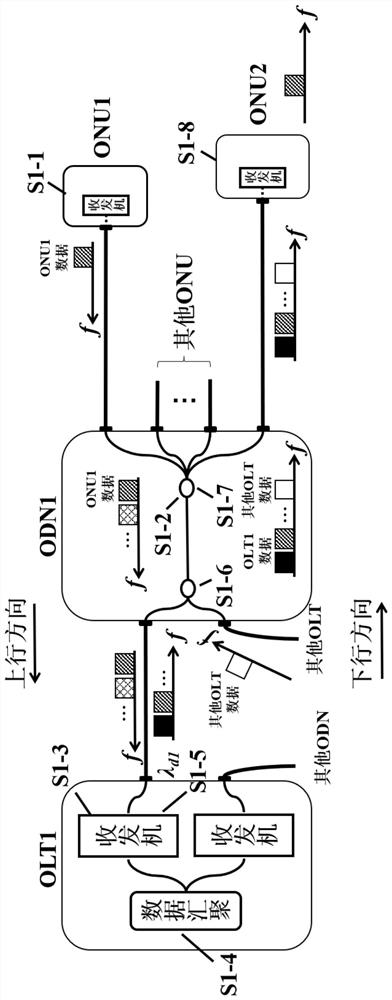
[0064] Such as figure 2 As shown, the present invention provides a method for mutual communication between ONU users connected to the same ODN, so as to solve the problem of mutual communication between ONUs connected to the same ODN. Suppose now that ONU1 wants to communicate with ONU2, the communication process is as follows:

[0065] The system designs the center frequency f of the subcarrier that transmits data for ONU1 connected to ODN1 1 , the data transmission bandwidth B and the guard interval Δf with other carriers are used for the modulation of ONU1 data; if other ONUs connected to ODN1 also need to send information, the center frequency f of the carriers of other ONUs k can be obtained by the formula f k =f k-1 +B / 2+Δf is calculated, where k=2,...,M.

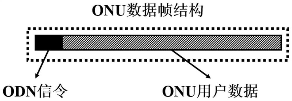
[0066] After the system pre-allocates subcarriers and bandwidth for each user, ONU1 generates ODN signaling indicating the destination address and its own data, forming a image 3The uplink data frame shown is m...

Embodiment 2

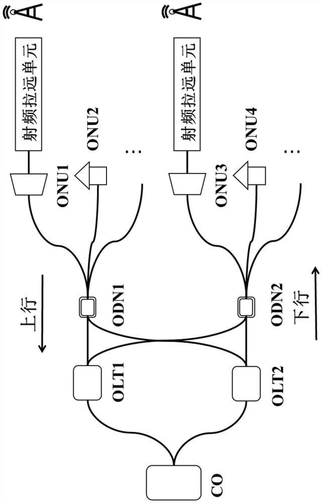
[0079] Such as Figure 4 As shown, this embodiment provides a method for mutual communication between ONUs connected to different ODNs under the control of the same CO. Suppose now that ONU1 wants to communicate with ONU2, the communication process is as follows:

[0080] The system designs the center frequency f of the subcarrier that transmits data for ONU1 connected to ODN1 1 , the data transmission bandwidth B and the guard interval Δf with other carriers are used for the modulation of ONU1 data; if other ONUs connected to ODN1 also need to send information, the center frequency f of the carriers of other ONUs k can be obtained by the formula f k =f k-1 +B / 2+Δf is calculated, where k=2,...,M.

[0081] After the system pre-allocates subcarriers and bandwidth for each user, ONU1 generates ODN signaling indicating the destination address and its own data, forming a image 3 The uplink data frame shown is modulated to the corresponding frequency band by the uplink signal ...


PUM


Abstract

The invention discloses a passive optical network architecture and an inter-ONU communication method based on the architecture, in the architecture, an OLT is connected with a plurality of ODNs, the communication method supports mutual communication between different ONUs under the control of the same CO without passing through the CO, in the communication method, the ONUs generate an uplink data frame containing uplink user data and target ODN address signaling, and the uplink data frame is used for sending the uplink user data and the target ODN address signaling to the OLT. The method comprises the following steps of: receiving uplink data by an OLT (Optical Line Terminal), modulating the uplink data to a pre-allocated subcarrier of a system by adopting a frequency division multiplexing technology based on subcarrier multiplexing, distributing downlink wavelength for the data according to address signaling information in the uplink data after the OLT receives the uplink data, and issuing the downlink wavelength to a target ODN (Optical Distribution Network) connected with the OLT, so that the data transmission of each user is only performed between the OLT and an ONU (Optical Network Unit), and the data transmission efficiency is improved. According to the invention, the CO is only responsible for sending the communication authority control instruction and controlling the downlink communication of the OLT, and does not process the uplink ONU data, thereby reducing the occupation of the storage space of the CO caused by the data between the ONUs under the control of the same CO entering the CO, and enabling the CO to meet the requirements of more cross-CO ONU communication.

Description

technical field [0001] The invention belongs to the field of optical communication, relates to passive optical network technology, and in particular relates to a passive optical network architecture and a communication method based on the architecture. Background technique [0002] With the development and progress of science and technology, the Internet of Everything, low latency, and high traffic have become the characteristics of modern networks. At the same time, with the gradual enrichment of telecommunications business content, users' demand for communication networks is also increasing year by year. Among them, the optical fiber access solution with the advantages of long distance and high capacity has gradually replaced other access network solutions such as coaxial cables, and has become a relatively mature solution for modern access network fiber-to-the-home. Among them, the passive optical network (Passive optical network, PON) uses passive devices for the link b...

Claims


Application Information

Patent Timeline
Patent Type & Authority Applications(China)
IPC IPC(8): H04Q11/00
CPCH04Q11/0062H04Q11/0067H04Q2011/0086
Inventor 周骥莫文轩王海德冯元华刘伟平
Why Eureka
Try Eureka