Resistance welding equipment

A technology of resistance welding and equipment, applied in resistance welding equipment, welding equipment, metal processing equipment and other directions, can solve problems such as low reliability, low production efficiency, welding quality problems, etc., to ensure welding quality, improve work efficiency, structure simple effect

Pending Publication Date: 2022-04-22
帅福得(珠海保税区)电池有限公司
View PDF1 Cites 0 Cited by
  • Summary
  • Abstract
  • Description
  • Claims
  • Application Information

AI Technical Summary

Problems solved by technology

However, when welding the product, it is necessary to manually hold the product and place the welded part in the middle of the welding needle for welding operation, which requires high labor and is prone to manual errors, resulting in welding quality problems and low production efficiency
An existing patent document with a publication number of CN203696226U proposes a resistance welding equipment. Although the degree of automation is relatively high and the work efficiency can be greatly improved, the welding equipment cannot detect whether the product is qualified for welding, and its reliability is relatively low.

Method used


Image

  • Resistance welding equipment
  • Resistance welding equipment
  • Resistance welding equipment

Examples


Embodiment Construction

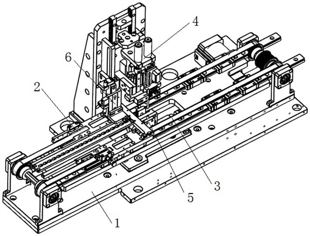
[0018] Such as Figure 1 to Figure 6 As shown, in this embodiment, the present invention includes a machine base 1, a tray positioning module 2, a conveying module 3, an upper welding module 4, a lower welding module 5 and a voltage detection module 6, and the conveying module 3. The upper welding module 4 and the lower welding module 5 are both arranged on the machine base 1, the tray positioning module 2 is arranged on the conveying module 3, and the voltage detection module 6 is arranged on the upper welding module 4, the tray positioning module 2 is located between the upper welding module 4 and the lower welding module 5, and the voltage detection module 6 is located in the tray positioning Module 2 above.

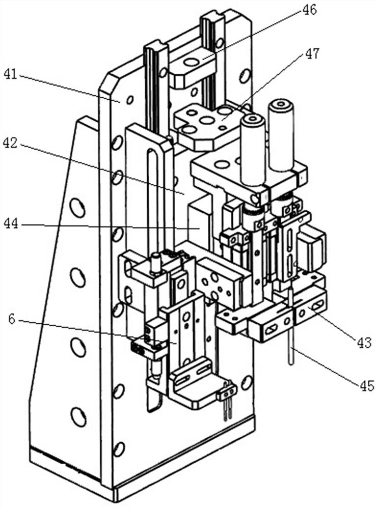
[0019] In this embodiment, the upper welding module 4 includes a support base 41, a mounting plate 42, a mounting base 43, a motor, an adjusting screw, a slide cylinder 44 and an upper welding pin 45, and the support base 41 is arranged on the On the machine base 1,...


PUM


Abstract

The resistance welding equipment is simple in structure, high in reliability and capable of improving the working efficiency and guaranteeing the welding quality. The automatic welding device comprises a machine base, a tray positioning module, a conveying module, an upper welding module, a lower welding module and a voltage detection module, the conveying module, the upper welding module and the lower welding module are all arranged on the machine base, and the tray positioning module is arranged on the conveying module; the voltage detection module is arranged on the upper welding module, the tray positioning module is located between the upper welding module and the lower welding module, and the voltage detection module is located above the tray positioning module. The method is applied to the technical field of welding.

Description

technical field [0001] The invention is applied in the field of welding technology, and in particular relates to a resistance welding equipment. Background technique [0002] At present, welding the connecting piece on the pin of the capacitor is to weld the connecting piece and the pin of the capacitor together by means of resistance welding. However, when welding the product, it is necessary to manually hold the product and place the welded part in the middle of the welding needle for welding operation, which requires high labor and is prone to manual errors, resulting in welding quality problems and low production efficiency. An existing patent document with a publication number of CN203696226U proposes a resistance welding equipment. Although the degree of automation is relatively high and the work efficiency can be greatly improved, the welding equipment cannot detect whether the product is qualified for welding, and its reliability is relatively low. If a kind of resi...

Claims


Application Information

Patent Timeline
IPC IPC(8): B23K11/00B23K11/11B23K11/36G01R19/165G01R31/54
CPCB23K11/002B23K11/36B23K11/115G01R19/16576G01R31/54
Inventor 吴子其盛腊元赵永照林健鸿何坚辉
Owner 帅福得(珠海保税区)电池有限公司
Why Eureka
Try Eureka