
Weld joint real-time tracking device based on laser vision

A real-time tracking and visual technology, applied in auxiliary devices, welding equipment, auxiliary welding equipment, etc., can solve the problems of difficulty in ensuring that the welding surfaces of steel plates are relatively parallel, the adjustment of placement, and the reduction of welding quality, so as to improve welding accuracy, Easy removal and placement, improved accuracy

Pending Publication Date: 2022-04-22
米开罗那(上海)工业智能科技股份有限公司
View PDF0 Cites 2 Cited by
  • Summary
  • Abstract
  • Description
  • Claims
  • Application Information

AI Technical Summary

Problems solved by technology

[0003] However, when using laser vision-based real-time seam tracking devices to weld plates, the steel plates to be welded are usually placed together directly. If the steel plates have a large area, it is difficult to ensure that the welding surfaces between the steel plates are relatively parallel. It may cause a decline in welding quality. At the same time, if the welded steel plate is a non-rectangular special-shaped structure, it is inconvenient to adjust the position of the steel plate during linear welding. During the welding process, impurities on the steel plate will also affect the equipment. For real-time sampling and tracking of weld seams

Method used


Image

  • Weld joint real-time tracking device based on laser vision
  • Weld joint real-time tracking device based on laser vision
  • Weld joint real-time tracking device based on laser vision

Examples


Embodiment Construction

[0029] In order to make the technical means, creative features, goals and effects achieved by the present invention easy to understand, the present invention will be further described below in conjunction with specific embodiments.

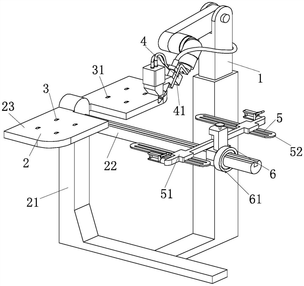
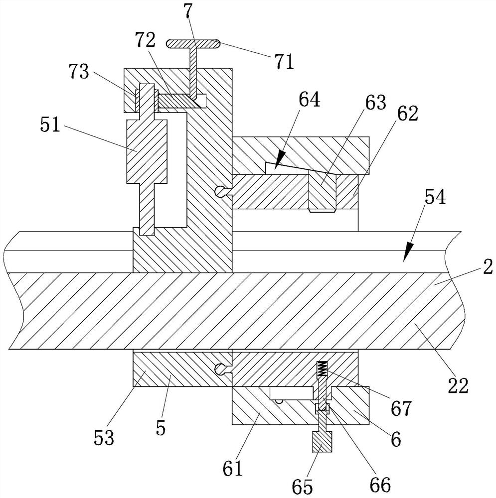
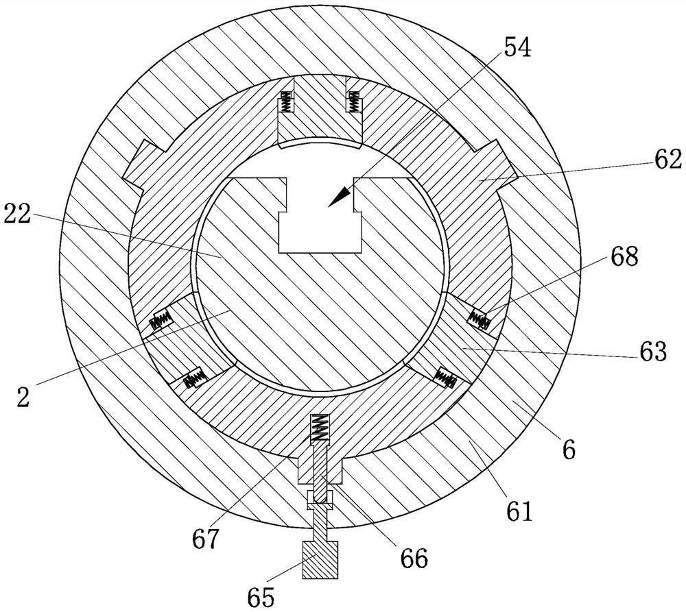
[0030] Such as Figure 1-Figure 9 As shown, the embodiment of the present invention provides a real-time tracking device for welding seams based on laser vision, which includes a welding equipment body 1, a bearing structure 2 is provided on the side of the welding equipment body 1; a moving Structure 3; the other side of the bearing structure 2 is slidably connected with a clamping structure 5; a positioning structure 6 is connected between the clamping structure 5 and the bearing structure 2; the top side of the clamping structure 5 is provided with a fixed Structure 7; a cleaning structure 4 is fixedly connected to the bottom side of the welding equipment body 1 .

[0031] Such as Figure 1-Figure 9 As shown, the bearing structure 2 includes a ...


PUM


Abstract

The invention provides a real-time welding seam tracking device based on laser vision. The real-time welding seam tracking device comprises a welding equipment body, and a bearing structure is arranged on the side face of the welding equipment body; a moving structure is arranged on the top side of the bearing structure; the other side of the bearing structure is slidably connected with a clamping structure; a positioning structure is connected between the clamping structure and the bearing structure; a fixing structure is arranged on the top side of the clamping structure; the bottom side of the welding equipment body is fixedly connected with a cleaning structure; a to-be-welded steel plate can be horizontally placed through the bearing structure, the welding accuracy is guaranteed, the steel plate with the large area can be conveniently moved through the moving structure, the welding sides of the two fixed steel plates can be kept parallel through the clamping structure, the width of a welding seam can be adjusted through the fixing structure, and the welding efficiency is improved. The welding seam between the steel plates can be accurately adjusted through the positioning structure, and dust at the welding position can be cleaned through the cleaning structure.

Description

technical field [0001] The invention belongs to the technical field of real-time tracking of welding seams, in particular to a real-time tracking device for welding seams based on laser vision. Background technique [0002] The welding seam tracking technology based on laser vision is to obtain the 3D position of the welding seam between the welding plates through the capture of laser and camera, so that the welding position can be adjusted independently through the computer, so as to realize intelligent unmanned welding and ensure the accuracy of welding To improve the efficiency of welding process. [0003] However, when using laser vision-based real-time seam tracking devices to weld plates, the steel plates to be welded are usually placed together directly. If the steel plates have a large area, it is difficult to ensure that the welding surfaces between the steel plates are relatively parallel. It may cause a decline in welding quality. At the same time, if the welded ...

Claims


Application Information

Patent Timeline
Patent Type & Authority Applications(China)
IPC IPC(8): B23K37/00
CPCB23K37/00
Inventor 万新军
Owner 米开罗那(上海)工业智能科技股份有限公司
Learn More